I have purchased a few low-distortion opamps from a local but rather reputable distributor.
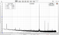
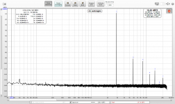
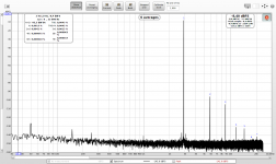
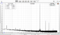
First comparison of 4556 measurements from last time and today. New REW version is used, perhaps the difference in measured THD can be attributed to the change of the fundamental level calculation (rms vs. amplitude). Nevertheless the shape of harmonics as well as their levels on the chart are basically identical, difference is only in the box with calculated distortions.
First comparison of 4556 measurements from last time and today. New REW version is used, perhaps the difference in measured THD can be attributed to the change of the fundamental level calculation (rms vs. amplitude). Nevertheless the shape of harmonics as well as their levels on the chart are basically identical, difference is only in the box with calculated distortions.
Attachments

None of the new opamps measured are "well behaving". THD grows much slower compared to the common-mode distortion multiplier. I took only screenshots of non-amplified THD.
I have used only older low-distortion models since my adapter requires dual-channel DIL8 opamps and I did not have time to order some SMD-DIL8 adapters.
Always two pieces were purchased and measured.
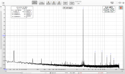
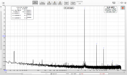
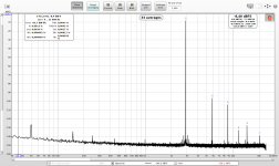
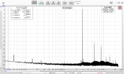
OP275GPZ - the measured distortion was way higher than specified. Both pieces measure identically. Fake/real?
I have used only older low-distortion models since my adapter requires dual-channel DIL8 opamps and I did not have time to order some SMD-DIL8 adapters.
Always two pieces were purchased and measured.
OP275GPZ - the measured distortion was way higher than specified. Both pieces measure identically. Fake/real?
Attachments
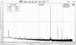
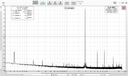
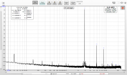
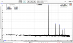
OPA2134PA - again much more distorting than specified. The distortion profile is almost identical to OP275 from the previous post, just slightly lower. Fake/real?
Attachments
Last edited:
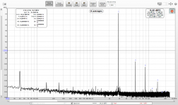
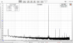
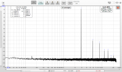
LM4562NA - the measured distortion is much lower, still much higher than specified. Higher THD than the consistently measured distortion of the 4556 ID1. Again the distortion profiles are very similar for the two pieces, yet completely different from the OP/OPA series.
Attachments
Last edited:
That hasn't changed. Check whether the View option "Full scale sine rms is 0 dBFS" is selected (default nowadays since AES recommend that).New REW version is used, perhaps the difference in measured THD can be attributed to the change of the fundamental level calculation (rms vs. amplitude).
Thanks for the clarification. Very likely my previous version setup did not have that checked (all RMS values were lower by 3dB).
Testing SO8 OPA2134 with SO8-DIL8 adapter. I added extra A23 battery to each supply line, replaced the small 22uF cap across the +/-lines with 1mF for each line to make sure the supply is stable.
Screenshots:
1. DIL8 OPA2134 1x : 0.0034%
2. DIL8 OPA2134 11x: (0.0043% - 0.0034%)/11 = 0.00008%
3. DIL8 OPA2134 48x: (0.0079% - 0.0034%)/48 = 0.00009%
4. SO8 OPA2134 1x: 0.0032%
5. SO8 OPA2134 11x: (0.0043% - 0.0032%)/11 = 0.0001%
6. SO8 OPA2134 48x: (0.0081% - 0.0032%)/48 = 0.000102%
IMO the OPA2134 common-mode distortion is around 0.0001%, the rest is some other distortion type. BTW that is almost exactly to the datasheet value 0.00008% but that is for complete THD+N - a very different meaning.
Honestly, I do not know how to get to the overall distortion in the datasheet. Maybe my adapter introduces some extra distortion (but for other opamps the THD measures below 0.0005% and scales well with common-mode gain). I still tend to conclude the measurements are correct.
Attachments

The E-MU 0404 headphone output is measurably more suitable than one line of the balanced outputs, due to its much lower output impedance (output serial resistor 22R vs. 560R). Loopback is clean, but connecting the opamp adapter changes the pre-calibrated output distortion profile. Much less for the stronger headphone output.
OPA1622s in DIP8 adapter to replace the headphone output 2114 are on the way, will take a month though, not available in Europe, as usual...
OPA1622s in DIP8 adapter to replace the headphone output 2114 are on the way, will take a month though, not available in Europe, as usual...
Talking about soundcards and their A/D distortion, have you investigated soundcard's response to input wideband noise that accompanies measured signal? The reason why I am asking is as follows:
Today I was servicing one of my fiber optic systems that are used for isolation of HV measurements. The systems uses frequency modulation of constant width impulses, this is then decoded by a steep low pass, analog system. It has carrier frequency of some 2MHz and bandwidth of some 300kHz. So, there is some wideband noise at the output of those systems, like -60dBV. I was curious how it would measure in audio band. Not so bad THD is about 0.2% up to 20kHz regardless frequency. I used a 96kHz/24bit sampling. However, I found that 3rd and higher order distortion (which are very low compared to dominating H2) components are strongly dependent on noise BW that goes into soundcard. That means, the soundcard is unable to handle input wideband noise, though the signal frequency was 1kHz. When I used a 2xRC low pass filter 20kHz, H3 component measured by the soundcard was 20dB lower than without the filter! That means that the soundcard is unable to handle input wideband noise and makes false measurements. I know you work with much lower noise of opamps compared to that fiber optic system, however your distortion components are also much lower. I am pretty sure that the wideband noise affects your measurements as well and that you should use an analog passive low pass for your measurements as well.
Today I was servicing one of my fiber optic systems that are used for isolation of HV measurements. The systems uses frequency modulation of constant width impulses, this is then decoded by a steep low pass, analog system. It has carrier frequency of some 2MHz and bandwidth of some 300kHz. So, there is some wideband noise at the output of those systems, like -60dBV. I was curious how it would measure in audio band. Not so bad THD is about 0.2% up to 20kHz regardless frequency. I used a 96kHz/24bit sampling. However, I found that 3rd and higher order distortion (which are very low compared to dominating H2) components are strongly dependent on noise BW that goes into soundcard. That means, the soundcard is unable to handle input wideband noise, though the signal frequency was 1kHz. When I used a 2xRC low pass filter 20kHz, H3 component measured by the soundcard was 20dB lower than without the filter! That means that the soundcard is unable to handle input wideband noise and makes false measurements. I know you work with much lower noise of opamps compared to that fiber optic system, however your distortion components are also much lower. I am pretty sure that the wideband noise affects your measurements as well and that you should use an analog passive low pass for your measurements as well.
Last edited:
Thanks a lot for your observation. While investigating the impact of the opamp measurement adapter, I learned this:
* no opamp in the DIP8 socket, non-inverting-input slot of the socket connected to output slot with a short pin wire.
* output switch switched to measurement - i.e. the soundcard output always feeds the opamp adapter, in addition to the permanently connected LPF/VD.
* split-sides calibration/compensation with headphones output, calibrated exactly at level of the opamp adapter output.
* when measuring spectrum of the LPF/VD, the harmonics are tamed to -150dB max. - the impact of the measurement adapter on the soundcard output is fully compensated by the calibration.
* upon flipping the input switch from LPF/VD to opamp adapter output, the third harmonic shots up to -130dB, even though the input signal level is identical down to 0.001dB - the calibration is exactly at this level.
That means somehow the much longer path through the opamp adapter (only two shielded balanced cables and a simple voltage divider at the output of the opamp socket) introduces quite a significant distortion. Very unlikely a real waveform distortion (no active components in path), but it could be the effect of the induced broadband noise you talk about.
I will make a small shielded female/male TRS junction with the filter inside to plug optionally into the soundcard input. Thanks for your suggestion.
Thanks for sharing your experience. Yes the numbers measured are so small that anything may be important.
When you get to these distortion levels the input cap modulation with voltage becomes significant. The source Z looking from the input needs to be very low to minimize its effect. Changes in the source Z will show as changes in distortion.
Yes, however e.g. JFET opamp input capacitance non-linearity is far more significant than non-linearity of a polypropylene or NPO/COG capacitor. Wideband noise effect to A/D distortion is higher than that of a polypropylene or NPO/COG cap.
The soundcard's Hi-Z inputs are DC-coupled, the first coupling capacitor is behind the 5532 input buffer.
5532s are bipolar, i.e. with bipolar input transistors.
I am designing the two-stage passive RC low-pass filter before the soundcard input. What input/output impedance would you choose? The soundcard's input impedance is 1M. The cutoff freq around 30kHz.
5532s are bipolar, i.e. with bipolar input transistors.
I am designing the two-stage passive RC low-pass filter before the soundcard input. What input/output impedance would you choose? The soundcard's input impedance is 1M. The cutoff freq around 30kHz.
I am designing the two-stage passive RC low-pass filter before the soundcard input. What input/output impedance would you choose? The soundcard's input impedance is 1M. The cutoff freq around 30kHz.
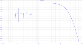
I have a filter like this (R4 represents output impedance of the preamp or generator, C1 = C2 = 4n7):
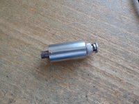
P.S.: photo attached
Attachments
Last edited:
My point was that the calculated compensation would be invalid if the source impedance into the ADC changes. The input amp on the Shibasoku shows the level of effort needed to reduce the input C distortion so it's not degrading the measurement. John Caldwell has some stuff on this in some TI notes as well. I could easily see the affect with the Shibasoku when connecting different devices to a 600 Ohm low distortion source at the device input.
PMA: thanks a lot, I will build something like that. The filter input impedance is around 1k within the audio range, that seems OK.
Demian: since the soundcard has 1M input impedance, how about e.g. 50k serial resistor with the input? That should effectively reduce the source impedance change. The potential frequency range reduction or phase shifts should not matter for this use case, IMO.
50k will be noisy. This would add about 30nV/rt(Hz) voltage noise, thermal noise in series with input. About 4uV/20kHz BW.
And putting big 50k resistor in series with input of the opamp will increase (not decrease) distortion. If you want to avoid influence of input frequency dependent non-linearity (including capacitive non-linearity), you need the lowest source resistance.
And putting big 50k resistor in series with input of the opamp will increase (not decrease) distortion. If you want to avoid influence of input frequency dependent non-linearity (including capacitive non-linearity), you need the lowest source resistance.
Last edited:
- Home
- Design & Build
- Equipment & Tools
- Digital Distortion Compensation for Measurement Setup