Inspired by the discussion here, I made these for my FE103En drivers. I used the cutouts from my 18" WA's - at least a better fate than the garbage can. That can happen in due time./QUOTE]
What material is that? 2" polystyrene? like stuff used for insulation.
Would pink noise with semi-octave bands of analysis "do" to assess the baffle step edge diffraction these things are making?
I would think a gated swept sine, with the speaker kept off the ground and away (360deg) from other objects would be sufficient to measure diffraction. The driver is not going very low so a short gate time (3ms) would be enough to try it indoors.
What would be the audible effect in your opinion in a "normally furnished" living room?
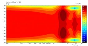
I will just refer you back to what Linkwitz wrote, and I quoted (I think in this thread?) that the on- and off-axis responses should be as similar as possible. When you have the "lines crossing" you are for example getting off axis beaming while you have an on axis null, or vice versa. If the response is EQ'd to be flat on axis, it will make the problem worse. These features tend not to go against what SL suggests is how to make the "room disappear" and the loudspeaker sound good.
The scale on the y-axis in Don's plot shows that these features are only a couple of dB in magnitude. It's up to you to decide what is acceptable, but that level of crossing is certainly not all that bad in my opinion.
It does seem quite small and over a relatively narrow angle, I could imagine listening near field with two ears 😉 it might even average out quite well?
From what I understand dipole constant directivity is only a major concern in a reverberant room, and a largish one at that, in a small room, on axis response is the most important.
I wonder what people reading this thread think are the advantages of OB speakers, I don't consider the torus or variations to be true dipoles.
Why is the torus not a dipole? Radiates out both ends and has a lateral null. Walks like a duck, sounds like a duck, looks like a duck.....
In my view it's not a "true dipole" because it doesn't have constant directivity. I also think this only matters in very specific circumstances. I think there is a good case for "near enough"
Charlie's attempts come close and that's a goal of his. I wonder if the compromises to achieve it are worth it.
Name a true dipole - if there is one?
Well, are you talking about a dipole or a dipole (see NOTE below)? There is certainly no driver that I am aware of that is a true point-like dipole at HF, or even is "dipole-like" from 20-20k (in a practical sense), and that includes ESLs. Using a slightly more loose definition of a dipole, it's more a question of "over what bandwidth is X a dipole" than whether it's a dipole.
For example, when used WITHOUT a baffle:
dipole ribbon tweeter - a dipole over it's entire operating range
dipole ribbon midrange - ditto, beaming may occur at HF
For LF, many large drivers with very open frames - e.g. Eminence Deltalite 2515
This is by no means an exhaustive list. Many drivers (e.g. "woofers") form a dipole pattern and it is just a matter of at what frequency does that break down.
The above trio can be combined into a true dipole system, from 100-20k Hz, using each driver within an appropriate band. Below 100Hz various types of dipole subwoofer systems can be used, e.g. M- or H-frame, OB, two CB subs operated as a dipole, etc.
NOTE:
I should clarify that I am not thinking of the "two point source" model of a dipole since that is not observed for any driver at HF. The size of the radiating surface needed to generate enough SPL for it to be useful as an audio transducer also makes it "too large" to be point-like at higher frequencies. The limit for "point-like dipole operation" is probably no more than 2kHz. Above this you can still get a "dipole" (meaning two lobes, one out of phase with the other and with a null at 90 degrees) pattern, which I think still qualifies for the "dipole" label even if not strictly so.
Last edited:
What material is that? 2" polystyrene? like stuff used for insulation.
I would think a gated swept sine, with the speaker kept off the ground and away (360deg) from other objects would be sufficient to measure diffraction. The driver is not going very low so a short gate time (3ms) would be enough to try it indoors.
Thanks, Don. It's actually 1.25" MDF, from a desktop that I'd used on another project. I'll give REW a shot with the short gate time.
Thanks, Charlie - for waking me up. I tried some EQ boost at 250 and it measures a little better with pink, but sounds terrible. There's no way I'll bring these down to match the sub I happen to have - or the sub up to match these; there'll always be a big notch in between what each driver system can reach. I realize all this should be in its own thread... vs hijacking this one.
Thanks Joe, I've not seen "white" MDF before. If you do measurements, and can be bothered with the extra work, it would be interesting to see what difference rounding or chamfering the edges makes.
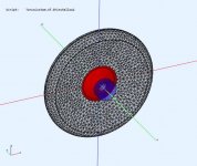
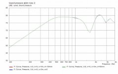
Don, do you mind, as a comparison, making it symmetrical, ie, moving the driver back to centre and making the exits the same front and back, a conical waveguide to near the edge?It's better than I was expecting. I think this improves it, because it reduced the 2K bump with little cost elsewhere. So it's good suggestion. The pic shows the axial response overlayed to compare them. The polars are similar for both.
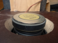
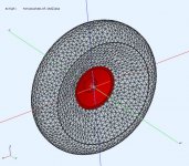
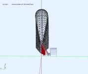
Sure, here it is. Similar dimensions to the previous (ID=150mm, OD=450mm, shallow conical exit symmetric). What are you looking for ?
.
.
Attachments
-
 TorusShallow2-front.jpg96.6 KB · Views: 258
 -
 TorusShallow2-rear.jpg95.4 KB · Views: 258
 -
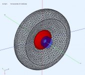
 TorusShallow2-Xsection.jpg46.6 KB · Views: 254
 -
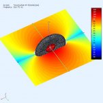
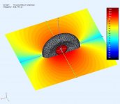 TorusShallow2-ObsField@500Hz.jpg45.3 KB · Views: 126
 -
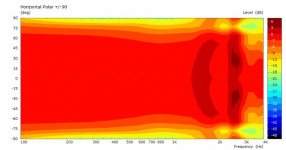 TorusShallow2-PolarContour@3m.jpg25.9 KB · Views: 135
 -
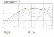 TorusShallow2-PolarCurves@3m.jpg46.4 KB · Views: 225
 -
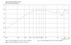 TorusShallow2-FR-SPL@3m.jpg33.5 KB · Views: 267
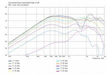
Thanks Don. That doesn't look too bad 20-30 degrees off axis 😉 I wanted to see how it compared to the original torus and how effective a simple conical waveguide is. I'm also looking for something relatively simple to construct using the starting point of a torus, ie an innertube, tyre or similar.
Why do you think it isn't as good as the last one, driver too deep?
Why do you think it isn't as good as the last one, driver too deep?
The differences were an attempt to smooth out the axial performance. The driver was offset (not centered to create a difference in exit delays) and the exit flares were different (differences from magnet+cone backside) attempting to offset to front/rear radiation peaks/dips. What ripple was left (IMO) could be reduced by making an irregular perimeter on the torus. It could also be further refined with some surface damping.
We can test your idea by making the torus thinner. My CAD models are parameterized so I change a dimension and get a new model 🙂
We can test your idea by making the torus thinner. My CAD models are parameterized so I change a dimension and get a new model 🙂
Last edited:
Perhaps we've been focusing too much on the notion of a torus, my idea stemming from what Earl Geddes said, it seems a shallow waveguide with a rounded edge works better.
This one has [ ID=150, OD=450mm, T=60mm] so the thickness and edge fillet was reduced (T=110mm on previous).
There are earlier torus versions presented where the torus was deep enough to make waveguides/horns for the front and rear exits. These are better IMO because they start to assert wavefront control @>1Khz and reduce the energy seen at the edges. They would still benefit from an irregular perimeter IMO. Always fun to see the outcomes.
.
Attachments
-
 TorusThinShallow-front.jpg61 KB · Views: 118
 -
 TorusThinShallow-rear.jpg59 KB · Views: 109
 -
 TorusThinShallow-Xsection.jpg26.3 KB · Views: 106
 -
 TorusThinShallow-Axial@3m.jpg33.7 KB · Views: 113
 -
 TorusThinShallow-PolarCurves@3m.jpg47.2 KB · Views: 120
 -
 TorusThinShallow-PolarContour@3m.jpg26.6 KB · Views: 113
 -
 TorusThinShallow-ObsField@519Hz.jpg37.3 KB · Views: 121
Last edited:
The simplest would be a square 😉 I did suggest that in one of the threads that spawned this one, no-one commented on it though..........They would still benefit from an irregular perimeter IMO.
Did you mention something triangular, like a wankel rotor?
I like the idea of keeping some semblance or symmetry around the perimeter
Last edited:
I'm really amazed at your ability to manipulate this program Don - many thanks - very instructive indeed.
When I was reading about Mattes baffles, I noticed that he used some quite dense rubber foam material and machined it to shape, (not moulded) an expensive process - I was wondering if this is to absorb driver vibrations/damping or effect higher freq radiating response (freq absorption) and if this could be included like the idea of absorbent material on the outside edge? Or if it would be at all significant?
Hi Scott, still following along slowly.
Is the focus on generating an even front radiating pattern preferable to smooth & extended freq response?
Some of the earlier models extended the low freq response and also have a pronounced dip around 2.5kHz would suit a number of accessible 8" FR drivers that have a cone resonance in that area - just saying …
- Home
- Loudspeakers
- Full Range
- Did Siegfried Linkwitz miss a trick?