^kaameelis
The ZIP file only has the toroid step file, the project is missing. The toroid is huge ID=350mm, OD=1150mm so its closer to a tractor tire than a wheelbarrow tire 🙂
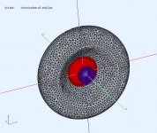
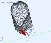
I've created a 1/4 symmetry model from your step file and added a driver. The woofer is a franken-driver I quickly "made up". You can use coarser mesh as a woofer of this size won't go past 2K without issues. The project file is in the link I PM'd you earlier. It solves in 10min on a 8 thread CPU.
The ZIP file only has the toroid step file, the project is missing. The toroid is huge ID=350mm, OD=1150mm so its closer to a tractor tire than a wheelbarrow tire 🙂
I've created a 1/4 symmetry model from your step file and added a driver. The woofer is a franken-driver I quickly "made up". You can use coarser mesh as a woofer of this size won't go past 2K without issues. The project file is in the link I PM'd you earlier. It solves in 10min on a 8 thread CPU.
Attachments
Sorry, file names where same and I zipped wrong file type.
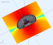
Now correct akp file is attached. I made torus so big to get comparison data with about same size U-frame for midrange.
Your made akp solves also on my PC in about 10 minutes, huge difference when simulation is made in clever way, not as my with brute force.
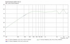
But what can be reason of so different results as on image? On my version measurement are taken 1 m from speaker center.
Now correct akp file is attached. I made torus so big to get comparison data with about same size U-frame for midrange.
Your made akp solves also on my PC in about 10 minutes, huge difference when simulation is made in clever way, not as my with brute force.
But what can be reason of so different results as on image? On my version measurement are taken 1 m from speaker center.
Attachments
Last edited:
Yes, Don, probably nothing in it - I wondered about it as Mattes is using a somewhat softer material that's not at all easy to work with so there must be a good reason for it - no doubt he's done much homework on this and without impinging on his design, it'd save us trying to 'reinvent the wheel'
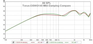
Fair enough. Here is the last model (OSWG140) with damping applied. The damping is 50% (absorption) starting at 500Hz simple 1st order. It does help smooth things out, especially in the polars, more than I thought. 🙂 The "purple" indicates where damping was applied.
.
Attachments


That has some potential. Of the tori, the one in post 126 still seems the best? I would be interested to see it with a shallower conical waveguide.
I can provide an example so you can see the effect but it will have to be tomorrow.
I also like 153 with irregular perimeter, maybe a combination of all of them (ala @mattes).
I also like 153 with irregular perimeter, maybe a combination of all of them (ala @mattes).
Last edited:
Thanks, no hurry, something similar to post 126 but with a shallower, cone extending nearer to the "edge" please. 🙂 Yes, 153 worked very well.
Even with the relatively mediocre results from the torus or waveguide shapes simulated, you only show the response on one axis (I assume it's "on axis"). To be more complete, it would be much more informative to show the frequency response for 0, 20, 40, 60 degrees (for example). If you can do a finer angular increment that would be great, too. Line plots are often much clearer WRT peak positions and other stuff. The heatmap presentation is OK for very general features, but it really is not all that helpful about the details.
Also, is there any (known) correspondence between the adsorptive layer you used (GM) that is supposed to represent some kind of felt or something, and actual thickness and type of felt in the real world?
Also, is there any (known) correspondence between the adsorptive layer you used (GM) that is supposed to represent some kind of felt or something, and actual thickness and type of felt in the real world?
If the torus simulation is compared to that of a flat circular baffle of equivalent diameter you can see how the on axis peaks and dips are far lower, in fact the largest ones at the dipole peak and the first dip above it are almost non-existent.
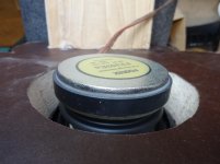
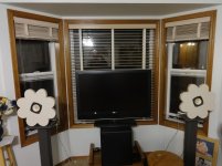
Inspired by the discussion here, I made these for my FE103En drivers. I used the cutouts from my 18" WA's - at least a better fate than the garbage can. That can happen in due time.
They sound like a pair of shirt-pocket transistor radios, with the sub turned off. I assume the sub cannot reach upwards of 200 Hz, so the system probably has a big hole there. I did bother to flare the back of the cutout, by first setting the saw at an angle. Unfortunately, I dont own a machine that can swing this diameter, to more precisely lathe off material for contours.
Otherwise, they sound like OBs. (The TV is stuck there temporarily)
It's been raining up here in the PNW, otherwise I could easily take one outside to measure. How should I measure, to correlate with the circular board measurement showing the worst case? I have REW, an appropriate ADC and mic and an amplifier.
Would pink noise with semi-octave bands of analysis "do" to assess the baffle step edge diffraction these things are making?
Attachments
Inspired by the discussion here, I made these for my FE103En drivers. ... They sound like a pair of shirt-pocket transistor radios, with the sub turned off. ... Otherwise, they sound like OBs.
Please tell us what EQ and crossover filtering are you using?
Thanks, no hurry, something similar to post 126 but with a shallower, cone extending nearer to the "edge" please. 🙂 Yes, 153 worked very well.
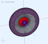
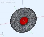
The same dimensions and driver offset as post #126 except a shallow front exit for the woofer.
.
Attachments
-
 Torus4f-shallow-front.jpg64.7 KB · Views: 197
 -
 Torus4f-shallow-rear.jpg67.8 KB · Views: 197
 -
 Torus4f-shallow-xsection.jpg53.9 KB · Views: 196
 -
 Torus4f-shallow-FR-SPL@3m.jpg33.3 KB · Views: 194
 -
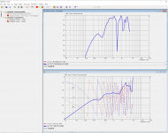
 Torus4f-shallow-FR-SPL-OffAxis@3m.jpg44.3 KB · Views: 197
 -
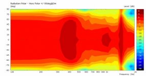
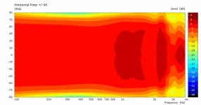 Torus4f-shallow-Polar@3m.jpg25.6 KB · Views: 112
 -
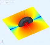 Torus4f-shallow-ObsField@519.jpg38 KB · Views: 111
Last edited:
>Please tell us what EQ and crossover filtering are you using
None on the FE103s. The highest frequency cutoff value the sub provides. (I just threw this together this week) The FE103s were in these little stock Akai T-line cabinets that they came with when I bought. I like the way they sound OB better.
None on the FE103s. The highest frequency cutoff value the sub provides. (I just threw this together this week) The FE103s were in these little stock Akai T-line cabinets that they came with when I bought. I like the way they sound OB better.
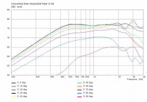
Even with the relatively mediocre results from the torus or waveguide shapes simulated, you only show the response on one axis (I assume it's "on axis"). To be more complete, it would be much more informative to show the frequency response for 0, 20, 40, 60 degrees (for example). If you can do a finer angular increment that would be great, too. Line plots are often much clearer WRT peak positions and other stuff. The heatmap presentation is OK for very general features, but it really is not all that helpful about the details.
See graph above, is this what you are looking for ?
Also, is there any (known) correspondence between the adsorptive layer you used (GM) that is supposed to represent some kind of felt or something, and actual thickness and type of felt in the real world?
Getting actual real material impedance data is difficult, even from companies that sell this material. I used a model that seems to correlate well with my carpet (from floor bounce experiments/measurements) so its not a total guess. I could have put an acoustic black hole around the driver. ABEC can accept impedance data files for more sophisticated modelling but you need to measure it and create the data file. There are a few good papers that I've read on how to extract impedance from either reflection, transmission, or absorption measurements. Its on my list as a winter project. 🙂
Perfect. This type of presentations shows, for example, some problems at 2.5kHz where the responses cross (some dip, some peak, and these lines cross each other). Only showing e.g. the on-axis response cannot reveal these issues.See graph above, is this what you are looking for ?
Getting actual real material impedance data is difficult, even from companies that sell this material. I used a model that seems to correlate well with my carpet (from floor bounce experiments/measurements) so its not a total guess. I could have put an acoustic black hole around the driver. ABEC can accept impedance data files for more sophisticated modelling but you need to measure it and create the data file. There are a few good papers that I've read on how to extract impedance from either reflection, transmission, or absorption measurements. Its on my list as a winter project. 🙂
OK, thanks on that. So by "correlate to my carpet" do you also mean the carpet's thickness, e.g. 1.5 cm thick or so? It's an important detail because someone could interpret that as 2mm of felt, which would be less effective.
>Please tell us what EQ and crossover filtering are you using
None on the FE103s. The highest frequency cutoff value the sub provides. (I just threw this together this week) The FE103s were in these little stock Akai T-line cabinets that they came with when I bought. I like the way they sound OB better.
The combination of the small, full-range driver, and a relatively small open baffle leads to a response that will start to roll off rather high, maybe as high as 800Hz and there will be a peak there. This is why it will sounds "like a transistor radio" as you say. You need to apply the right kind and amount of EQ to get a more acceptable tonal balance from this combo of driver and baffle.
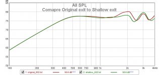
Thanks Don, that's interesting, is it better or worse than you expected? It's flattened the response more and pushed a peak up in frequency from 2 to 3k.The same dimensions and driver offset as post #126 except a shallow front exit for the woofer.
.
What would be the audible effect in your opinion in a "normally furnished" living room?Perfect. This type of presentations shows, for example, some problems at 2.5kHz where the responses cross (some dip, some peak, and these lines cross each other). Only showing e.g. the on-axis response cannot reveal these issues.
Perfect. This type of presentations shows, for example, some problems at 2.5kHz where the responses cross (some dip, some peak, and these lines cross each other). Only showing e.g. the on-axis response cannot reveal these issues.
It also shows in the polars provided which are normalized to 0deg (axial). You see it as an increase w.r.t 0deg.
OK, thanks on that. So by "correlate to my carpet" do you also mean the carpet's thickness, e.g. 1.5 cm thick or so? It's an important detail because someone could interpret that as 2mm of felt, which would be less effective.
It's a 44oz carpet on 3/8" foam underpad, I don't know how that translates to thickness, fiber diameter, fiber density and effect of the underpad. It was a simple first order approx. I don't know how you could extrapolate it to another material, I haven't done enough tests.
Thanks Don, that's interesting, is it better or worse than you expected? It's flattened the response more and pushed a peak up in frequency from 2 to 3k.
It's better than I was expecting. I think this improves it, because it reduced the 2K bump with little cost elsewhere. So it's good suggestion. The pic shows the axial response overlayed to compare them. The polars are similar for both.
Attachments
- Home
- Loudspeakers
- Full Range
- Did Siegfried Linkwitz miss a trick?