Jan do you do anything to assure the null is at a bin center, I have found that you can have several dB's of error especially if the null is exactly between bins. There is an argument to deliberately de-Q a notch to lower the artifacts when the center drifts a little with temp/time.
I haven't with the RTX & REW so far, no. Set the REW generator at 3004Hz (that's where my Victor seems to go and stay) for the ref for REW, and used a window.
Jan
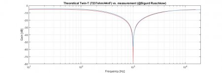
Here is a comparison of the Sigurd's measured response of the balanced Twin-T notch filter with a theoretical model of a single-ended filter.
The only correction made was lowering the gain of the simulation by 5.3dB to achieve agreement with the measurement in the range past the notch frequency because the filter in the simulation was not loaded.
The resistance and capacitance values used for the model are from the Victor's schematic.
The simulation was performed in Matlab.
Regards,
Braca
Attachments
@Braca, When used for reconstruction of the residual and/or calculating the real distortion, only the response above the notch frequency matters. In this case it looks reasonably accurate.
Cheers,
E.
Cheers,
E.
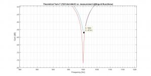
I measured every cap (22nF 1% COG) and they were all within 0,5% which is the tol of the cap meter.
Resistors are 0,1% and I did not measure them.
Using Diana, I get a notch freq of 1002,8 Hz and a notch depth of -68dBFS.
Resistors are 0,1% and I did not measure them.
Using Diana, I get a notch freq of 1002,8 Hz and a notch depth of -68dBFS.
Here is a comparison of the Sigurd's measured response of the balanced Twin-T notch filter with a theoretical model of a single-ended filter.
The only correction made was lowering the gain of the simulation by 5.3dB to achieve agreement with the measurement in the range past the notch frequency because the filter in the simulation was not loaded.
The resistance and capacitance values used for the model are from the Victor's schematic.
The simulation was performed in Matlab.
Regards,
Braca
Well, the frequency difference is 0.2%, so you're well within the tolerance limits 🙂.
As a possible Twin-T filter definition input, the model needs only three coefficients and the filter insertion loss in order to calculate the gain and phase values at any frequency.
In the case of a Hall topology filter, the number of coefficients would be six (it is a third order filter).
The insertion loss can be determined with LtSpice (I compared it with measurements, and it was good), or measured with REW or a similar software.
As already remarked, it would need complex number arithmetic in the software, but I don't think this is a problem.
Regards,
Braca
Attachments
Last edited:
I think a failing would be to use the residual fundamental to gauge the pre notch fundamental level. The B&K passive notch I'm using has around 80 dB insertion loss at the notch but even .05% shift will produce a 6 dB shift in level. At H2 and H3 its not particularly critical or even significant.
Most audio analyzers ignore the post notch fundamental and internally AGC the pre-notch level to an internal optimum. I think something similar with two channels could be implemented.
Most audio analyzers ignore the post notch fundamental and internally AGC the pre-notch level to an internal optimum. I think something similar with two channels could be implemented.
In that case your AV scanner is infected with heuristic false positive rubbish.

Just disable it.
Just disable it.
In that case your AV scanner is infected with heuristic false positive rubbish.
Just disable it.
Attachments

Hi soongsc,
Give me your email address and I will send you the latest version (1.60.6).
Cheers,
E.
Give me your email address and I will send you the latest version (1.60.6).
Cheers,
E.
Same here, 1.58.10 just dies quietly leaving no message of any sort.
I'm happy to report 1.60.6 works fine on Win 10 Pro 2004.
thank you, seems the site is down
best regards
Pio
mmm.... tried to download the demo version and run it, but the antivirus software interferes just after downloading... 🙁
What's wrong with this software?
False positive
Note that the majority of AV scanners has no issues with DiAna.
Cheers,
E.
Nothing! There is something wrong with your antivirus scanner that is whining about a so called false positive. Disable that POC or buy a decent AV scanner. 🙂mmm.... tried to download the demo version and run it, but the antivirus software interferes just after downloading... 🙁
What's wrong with this software?
Note that the majority of AV scanners has no issues with DiAna.
Cheers,
E.
Hi Pio,thank you, seems the site is down
best regards
Pio
No, that site is not down. Maybe it is blocked by your browser.
Cheers,
E.
- Home
- Design & Build
- Equipment & Tools
- DiAna, a software Distortion Analyzer