Yes for me the external notch lowers the signal dynamic range by say 60dB, so the soundcard or whatever intrinsic distortion looks 60dB lower.
But it is not critical to know exactly the notch depth; what is critical is to know the original fundamental level and any harmonic attenuation.
Maybe an example to clarify my thinking. Suppose my DUT delivers a 2Vrms signal, +6dBV. I also know that the notch attenuates the 2nd by 8dB.
So for the measurement, I scale in dBr, and set the dBr reference to -2dBV.
So the exact notch attenuation is not critical, as long as it is deep enough to keep the soundcard (or RTX) distortion out of the way. No problem if it slowly drifts (within reason of course).
In a two-channel soundcard, one could input the DUT output into one channel for level and frequency measurement and into the other channel through the external notch for distortion measurement. If the notch has been characterized before, no further need to enter numbers.
That is why I abandoned the design of the tracking notch, and instead now use the sync on the oscillator, so I do not need a window on the FFT even if it is a long one.
Jan
Last edited:
Understood so far. But why you don't need a window? Perhaps because the FFT record contains exactly a whole multiple of fundamental sines? Or are you talking about DiAna?[...]
That is why I abandoned the design of the tracking notch, and instead now use the sync on the oscillator, so I do not need a window on the FFT even if it is a long one.
Jan
Cheers,
E.
There were in fact two minor issues (one software, one hardware), that together caused the problem. As you know, during "Characterize notch filter" a sawtooth is superimposed on the fundamental. However, as result of some experimentation this sawtooth was disable on the notch channel (and later on I forgot to re-enable it).Hi Demian,
In the meantime I discovered that the option "Characterize notch filter" is broken since the last couple of updates. [...]
PS or is it a simple wiring issue?
Cheers,
E.
But at the same time both channels were summed together inside my filter box, so this sawtooth was still there on both channels (although at half the amplitude). That's the reason I didn't notice the error. I've repaired this bug and uploaded a new file, version 1.59.3. Note that this is not the version that I'm currently working on. That one comes later.
BTW, finding the notch frequency has been automated. Set the reference and notch channel as usual, select the 'Find notch frequency' and press the Monitor button.
When the phase, displayed in the status-bar, is near zero, the job is done. The frequency is also displayed in the status-bar and distortion preference page.
Cheers,
E.
Understood so far. But why you don't need a window? Perhaps because the FFT record contains exactly a whole multiple of fundamental sines? Or are you talking about DiAna?
Cheers,
E.
Yes. I think we should strive to be able to do without a window for best results. ANY window causes spectral leakage. With a stable oscillator, and control over the FFT process, that becomes a no-brainer, no?
Jan
Jan,
I'm not sure what software you are using and how much control you have, so I would say: the proof of the pudding is in the eating.
Cheers,
E.
I'm not sure what software you are using and how much control you have, so I would say: the proof of the pudding is in the eating.
Cheers,
E.
Sure. But a window for FFT is a bandaid to try to fix a problem and not completely succeeding, no? 'Noodzakelijk kwaad' we would say in Dutch (sorry guys).
Jan
Jan
I think Scott Wurcer had a brush with the subject
I built a passive 600 Ohm L/C filter for a Sound Technology 1700B to get its -106dB down to ~ -145dB back in the day when there was no AP. The coils were hand wound onto wooden forms.
Jan,
I'm not sure what software you are using and how much control you have, so I would say: the proof of the pudding is in the eating.
Cheers,
E.
As I see it Jan is using a mostly hardware trick, an AD that has an external clock which also injection locks the precision oscillator. The software problem goes away. Jan, I assume any soundcard that uses the same clock for DAC and A/D could sync the oscillator with the second channel?
We have several threads going on here skinning this cat different ways.
FFT windows
Cheers,
E.
To all,
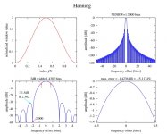
Please, Never ever call the raised cosine window (a popular one) a Hanning window, Grrr. It should be called Hann window, named after Julius von Hann.
A Hamming window is another story, named after Richard W. Hamming.
The purpose of a window is to avoid spectral leakage (and side lobes), a necessity when a whole number of (fundamental) periods doesn't exactly fit in a FFT record, i.e. when the 1ts sample of one record doesn't coincide with 1st sample of the next record. In that case the abrupt transition at the record boundaries will cause spectral leakage. A window will smooth out these unwanted transitions.Yes. I think we should strive to be able to do without a window for best results. ANY window causes spectral leakage. With a stable oscillator, and control over the FFT process, that becomes a no-brainer, no?
Jan
Cheers,
E.
To all,
Please, Never ever call the raised cosine window (a popular one) a Hanning window, Grrr. It should be called Hann window, named after Julius von Hann.
A Hamming window is another story, named after Richard W. Hamming.
Last edited:
The purpose of a window is to avoid spectral leakage (and side lobes), a necessity when a whole number of (fundamental) periods doesn't exactly fit in a FFT record, i.e. when the 1ts sample of one record doesn't coincide with 1st sample of the next record. In that case the abrupt transition at the record boundaries will cause spectral leakage. A window will smooth out these unwanted transitions.
Cheers,
E.
To all,
Please, Never ever call the raised cosine window (the popular one) a Hanning window, Grrr. It should be called Hann window, named after Julius von Hann.
A Hamming window is another story, named after Richard W. Hamming.
PM for the password! 🙂
The purpose of a window is to avoid spectral leakage (and side lobes), a necessity when a whole number of (fundamental) periods doesn't exactly fit in a FFT record, i.e. when the 1ts sample of one record doesn't coincide with 1st sample of the next record.
You guy are talking about two different things, all window functions have side lobes that can limit resolution (you can't get something for nothing). This is the best survey of windowing I have found (picture is from this reference). BTW Jan is talking about a method to lock the signal to exact bins needing no windowing, just another technique.
Spectrum and spectral density estimation by the Discrete Fourier
transform (DFT), including a comprehensive list of window
functions and some new flat-top windows.
G. Heinzel∗
, A. Rudiger ¨ and R. Schilling,
Max-Planck-Institut fur ¨ Gravitationsphysik
(Albert-Einstein-Institut)
Teilinstitut Hannover
February 15, 2002
Attachments
Huh? Those Germans call it a Hanning window? Grrrr. A good reason to not read that stuff. 🙂
More seriously, no window at all (i.e. a rectangular window) gives also rise to leakage (depending on the continuity of the input). Applying windows is just a matter of distributing the leakage in another way over the spectrum. Some windows increase the resolution, while other windows increase the accuracy (of the magnitudes).
More seriously, no window at all (i.e. a rectangular window) gives also rise to leakage (depending on the continuity of the input). Applying windows is just a matter of distributing the leakage in another way over the spectrum. Some windows increase the resolution, while other windows increase the accuracy (of the magnitudes).
Last edited:
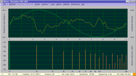
I think I'm making progress. I downloaded your latest version. Attached are two files with the notch in (in frequency mode). One is the distortion analysis and the other is the coherent spectrum. I think its saying that it measured the notch insertion as 80 dB? which could be right and a real PITA to tune manually. but that also shows all the harmonic stuff well below -140 which would be right but harmonic analysis suggest H2 is -126 which seems much higher than it should be at around -140 dB.
Attachments

Great!I think I'm making progress.
I don't know, but you might click on the lower left border to select one of three references options:I downloaded your latest version. Attached are two files with the notch in (in frequency mode). One is the distortion analysis and the other is the coherent spectrum. I think its saying that it measured the notch insertion as 80 dB?
1. Absolute. Now you can readout the absolute magnitude of H1 in dBV and manually compute the notch attenuation.
2. Relative. Harmonics magnitudes are relative to the magnitude of H1.
3. Reference. Harmonics magnitudes and H1 are relative to amplitude of the reference signal. Now you can readout directly the notch attenuation at H1.
Didn't the option "Find notch frequency" work? If so, then it's real PITA!which could be right and a real PITA to tune manually.
Note that the notch filtered signal should be large enough, otherwise it will fail.
Sorry, I've no explanation for this discrepancy. Max. 1 dB is acceptable because these spectra are computed in two total different manners, but a difference of 14dB is way too large.but that also shows all the harmonic stuff well below -140 which would be right but harmonic analysis suggest H2 is -126 which seems much higher than it should be at around -140 dB.
I've repeated your experiment (of course with my own notch filter) and an RTX. Then the discrepancy between the two 2nd harmonics was only 0.55dB.
What about the option "Apply notch compensation"? Does it work now?
NB: This option only applies to the THD spectrum (not the other two).
Cheers,
E.
Last edited:
More seriously, no window at all (i.e. a rectangular window) gives also rise to leakage (depending on the continuity of the input).
I thought that was Jan's point he is locking the A/D clock to the input so at "96kHz" sample rate there are always exactly 96 samples per cycle (at "1kHz" input) even if the oscillator drifts slowly. In this way an un-windowed FFT has every harmonic exactly in a bin and all other bins have a noise BW of 1Hz with no contribution from leakage. The drift on Viktor's oscillator is very slow especially with some warm up so the frequency locking loop works pretty well (from what I have seen).
@Scott, if that is the case (which wasn't clear to my immediately, hence my question/remark), then no FFT windows isn't needed at all. BTW, the THD FHT of DiAna works -more or less- in a similar way, also without a window. In this sense Jan and me are on the same track.
Cheers,
E.
Cheers,
E.
@Scott, if that is the case (which wasn't clear to my immediately, hence my question/remark), then no FFT windows isn't needed at all. BTW, the THD FHT of DiAna works -more or less- in a similar way, also without a window. In this sense Jan and me are on the same track.
Cheers,
E.
Yes, I said a different way to skin the cat. There is a third major effort here to mathematically remove the distortion from an ordinary sound card so in loop-back mode (DAC and A/D on same clock) we have the same general result. Maybe Jan has more details but IIRC an early version of AP software also did the re-sampling math to force synchronous FFT's. All good stuff and all should converge on the same answer as a sanity check. I am skeptical about any claims of -160dB measurements in general without independent verification.
Last edited:
Great!
What about the option "Apply notch compensation"? Does it work now?
NB: This option only applies to the THD spectrum (not the other two).
Cheers,
E.
I'm guessing on how this should work and maybe some specifics would help.
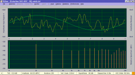
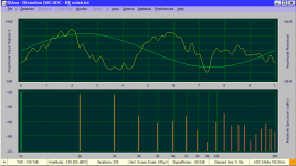
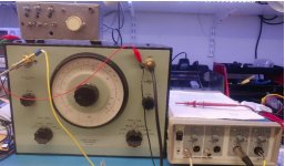
This is RTX loopback. The generator is set to 2V, analyzer set to 31V going though the B&K tuned as closely to the 994 Hz the generator is set to (to match the victor I have). Ch B is reference and CH A is test. The picture may help explain the setup. The B&K is very touchy to tune.
When I switch from normal to notch compensation it does change the amplitude relationships. The pictures are with the compensation on.
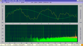
Final picture is with the B&K in the "linear" or bypassed position to see what I get directly.
I believe the process for characterizing the notch is to select it in options then run a distortion test. Then engage compensation. I saved the compensation file and included it. When I measure the notch I get around 69.5 dB loss at 994 Hz and 10 dB at 1998 Hz and 6.95 dB at 2982 Hz. I think this matches the file reasonably well.
The remaining question has to do with the two plots and whether anything can be inferred about level from the coherent plot and how to do it.
If this is the right process I'll try on my Victor (the little box on top of the B&K) again. Maybe in parallel with the Shibasoku. And with a function generator with enough distortion that it should not be stressing the measurements in any way.
Attachments
I thought that was Jan's point he is locking the A/D clock to the input so at "96kHz" sample rate there are always exactly 96 samples per cycle (at "1kHz" input) even if the oscillator drifts slowly. In this way an un-windowed FFT has every harmonic exactly in a bin and all other bins have a noise BW of 1Hz with no contribution from leakage.
That is more or less how we did this in the V97000 mixed signal wafer testers, although
the frequencies were absolutely stable. There is no point in acquiring long time series
and then throwing away half the energy in the outskirts of a cos-something function.
Tester time is precious.
BTW don't get fooled by the crystals in the notch filter above. It is on-topic.
Crystals are nothing but series RLC, maybe with weird numbers in their equivalent circuit.
The LC parts have no stress from the large fundamental, a definite advantage against filters
that subtract similar large values with op amps to get something near 0.
cheers, Gerhard
Last edited:
The purpose of a window is to avoid spectral leakage (and side lobes), a necessity when a whole number of (fundamental) periods doesn't exactly fit in a FFT record, i.e. when the 1ts sample of one record doesn't coincide with 1st sample of the next record. In that case the abrupt transition at the record boundaries will cause spectral leakage. A window will smooth out these unwanted transitions.
Cheers,
E.
Yes. As described earlier, I calculated the frequency that would fit an integer number of cycles in the FFT record and still be as close as possible to the twin-tee 3 kHz notch. I came up with 206 cycles of 3002.9 Hz, so set the AP digital generator to 3002.9 Hz and synced Vic's 3 kHz oscillator to that.
I then did a long acquisition (4MS's) with no windowing and send the file to Pavel, who analyzed it and confirmed the exact 3002.9 Hz fundamental, and his graphs shows zero spectral leakage.
Jan
- Home
- Design & Build
- Equipment & Tools
- DiAna, a software Distortion Analyzer