If you're not yet using DC Link capacitors as cathode bypasses, I strongly recommend you order a pair. I'm using Vishay and Kemet 40uF. Vishay gives slightly better treble, Kemets have a slightly richer midrange. WIMA and Epcos also make them. I'm pretty sure you'll hear an increase in clarity over electrolytics or other polypropylenes. I'm also using a 15uF DC Link as the last capacitor in the PSU. That makes a difference too.
andyjevans: How do DC-Link capacitors differ from regular film capacitors? I have used film caps for cathode bypass in past builds, and have used larger than normal chassis to fit them in.
andyjevans: I’ll order some on the next Digikey order. Is there a particular sku I should be looking for? At the moment the amp has Elna Silmic II on the 30 cathodes. The power supply is split at the final node for the 30s, and the last capacitors are 2.2 uF film caps. I do this on all amps for the final node to the driver tubes.
Up to you what values you go for. I did a shootout using cathode bypass on a 300b amp and the DC Link caps were audibly better than Clarity Cap polypropylenes, generic electrolytics and motor run caps. Vishay is more focussed, Kemet a little richer. Haven't auditioned Epcos or WIMA.
.Up to you what values you go for. I did a shootout using cathode bypass on a 300b amp and the DC Link caps were audibly better than Clarity Cap polypropylenes, generic electrolytics and motor run caps. Vishay is more focussed, Kemet a little richer. Haven't auditioned Epcos or WIMA.
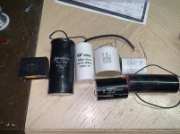
I have used a few different film caps. I have tried a number of large surplus film caps and ASC cans for cathode bypass. Values have always been 100 uF down to 40 iF. I have not compared different bypass caps in the same amp. In general, when I’m building a “serious” amp, I don’t use any electrolytics at all if possible. In the past this has been more about longevity of parts than sound quality. I have a large stash of biggish film caps. This is an assortment of the caps of which I have several of each. Will the DC-Link be noticeably better?
Attachments
.
I have used a few different film caps. I have tried a number of large surplus film caps and ASC cans for cathode bypass. Values have always been 100 uF down to 40 iF. I have not compared different bypass caps in the same amp. In general, when I’m building a “serious” amp, I don’t use any electrolytics at all if possible. In the past this has been more about longevity of parts than sound quality. I have a large stash of biggish film caps. This is an assortment of the caps of which I have several of each. Will the DC-Link be noticeably better?
Well, you can do your own shootout in the same amp by using clip leads and attaching your various caps one by one as cathode bypasses on the outputs. I was quite surprised at what I heard. Also watch out if you are switching caps that you discharge the voltage on them - you can get unexpected shocks! (....as I did)
The DC link caps were audibly clearer than 2 good polypropylene caps - ICW PW series and very big ICW Clarity Caps rated 630v. Since these look to be comparable to the caps you pictured, my bet would be that yes, you will hear an improvement. And more so if you also use them as the last caps in the PSU. Try it and let us know.
The DC link caps were audibly clearer than 2 good polypropylene caps - ICW PW series and very big ICW Clarity Caps rated 630v. Since these look to be comparable to the caps you pictured, my bet would be that yes, you will hear an improvement. And more so if you also use them as the last caps in the PSU. Try it and let us know.
I’ll have to order some as I don’t have any at hand. In the 30/6P15P-EV amp, the resistor cap did sound better than the LED. I’m not sure about other bias methods for the 30s that avoid capacitors, such as battery bias, back bias, etc. as I haven’t tried them. Had there not been an issue with the filament power transformer passing noise through to the filament regulator, this amp would not have required a capacitor at all on the 30. The 30 being what it is, with its very small heater requirements, and it’s design as a battery tube, a battery powered heater should be entirely workable, and much, much simpler and cheaper to implement. Not sure how it will sound though. Have you tried battery powered filaments?
A 2.2uf as the last cap in the PS seems awfully small to me. Is there some reason for using such a low value?andyjevans: I’ll order some on the next Digikey order. Is there a particular sku I should be looking for? At the moment the amp has Elna Silmic II on the 30 cathodes. The power supply is split at the final node for the 30s, and the last capacitors are 2.2 uF film caps. I do this on all amps for the final node to the driver tubes.
I typically use somewhere between 15uf and 50uf but I can't say I've really done any A-B comparisons.
Since I've been using battery bias on the input tube grids, and the cathode of the 6N6G output tube is internally biased and connects directly to ground, I have no need for cathode bypass caps. I've used the Panasonic DC Links but only in the PS. Perhaps I'll try some of the Vishays or Kemets that Andy suggests.
I have to wonder if some of the parts and/or configurations that sound best when listening full range might be considerably less noticeable when the amp is limited to treble duty, as you intend. I think I would want to voice it using the crossover. Or have you been doing that?
A 2.2uf as the last cap in the PS seems awfully small to me. Is there some reason for using such a low value?
I typically use somewhere between 15uf and 50uf but I can't say I've really done any A-B comparisons.
Since I've been using battery bias on the input tube grids, and the cathode of the 6N6G output tube is internally biased and connects directly to ground, I have no need for cathode bypass caps. I've used the Panasonic DC Links but only in the PS. Perhaps I'll try some of the Vishays or Kemets that Andy suggests.
I have to wonder if some of the parts and/or configurations that sound best when listening full range might be considerably less noticeable when the amp is limited to treble duty, as you intend. I think I would want to voice it using the crossover. Or have you been doing that?
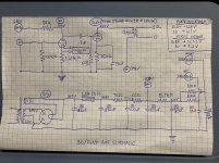
FlaCharlie: The attached schematic is not exactly what is in the amp at the moment, but the power supply is close to the same. B+ for the power tubes comes off 100 uF capacitor D. There is then a resistor, 33 uF capacitor E, and then the supply splits for the left and right 30 tubes. At this point there is a 10K Ohm resistor with its own 1.5 uF to ground for each tube, and then the plate resistors. I have been doing this for years after noticing it done in a commercial amp schematic. The theory is that this serves to better decouple the channels from each other. Do you think the last cap needs to be bigger for a 30 tube's B+? The B+ is super duper clean in this amp. Arguably, unnecessarily clean. When I want to do it "right", I replace the 5.1K resistor with a small choke for even more decoupling from the power supply node feeding the power tubes.
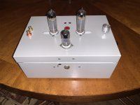
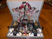
In my opinion, as an ideal, every tube should have its own power supply. I built an amp a while back that has a seperate power supply for each EL84 power tube, and a seperate choke input power supply for the driver tube. This is three power supplies for a three tube amp. I have done a couple of amp builds with three power transformers. It is built into an antique cash box. I have attached a couple of photos.
My plan for my upcoming big 300B amp is for a separate power supply for each 300B, and probably one shared supply for the two driver tubes, with two chokes to decouple the channels from each other that would replace the two 10K resistors in the attached schema. Either that or a separate supply for each driver tube as well. In my experiments and listening, I found that separate supplies sound better, and that decoupling where possible sounds better than not decoupling.
Attachments
A 2.2uf as the last cap in the PS seems awfully small to me. Is there some reason for using such a low value? I typically use somewhere between 15uf and 50uf but I can't say I've really done any A-B comparisons.
Yes - "somewhere between 15uf and 50uf" is what I use, exactly that.
I use filament bias with a choke loaded supply and Rod's regs on all these DHTs to get a small cathode resistor, and a plate choke of 150H or more with teflon caps. This always sounded best to me. I tried battery bias and SIC diodes but always came back to filament bias with a very clean supply. I haven't tried battery bias recently but I've used SIC diodes recently.
andyjevans: Easy enough to up the value of the last two caps. I’ll try it out. Is there a formula for final capacitor size? Each 30 has its own capacitor.
Your preferred method makes perfect sense for the majority of DHTs, and using it will work well with the 30, but the 30 is a battery tube with very small filament requirements. The current draw is only 60 mA. The difference between building a regular indirectly heated tube amp, and one that contains a DHT is pretty much a couple of batteries, some resistors and maybe a rheostat in the case of the 30. It’s a unique opportunity to provide a DHT front end because of the very efficient battery filament.
I will try a choke load and filament bias together when I build an 01A or 26 based project. I want to keep the 30 portion super simple for my next build. Battery filaments, battery bias or back bias (as posted by jhstewart9), plate resistor and maybe cathode resistor. The battery filament should make it quiet enough so that the capacitor is not needed on the cathode bias resistor. If it’s battery bias, there will be no cathode bias resistor. I might try the choke plate load as well. After taking so long on the last one, I think I can finish this new one very quickly given its simplicity. We will see how it sounds. There will be plenty of room to switch things up in the next one if batteries don’t work out.
The execution of a battery supply appears to be very simple, It’s a battery (or several batteries), a resistor and maybe a rheostat. The question is what kind of batteries are best?
Last edited:
Tizman...enough with 300B, lets play with some TT tube at the output. May be class A2?
Regards
Yes, eventually. I have pair of 300Bs and a few 45s that need amps built for them first. I have all the parts.
Most of DHT tubes hasn't enough gain (40...70) to drive (100-150Vpp) larger output tubes even at A1 region.
You must to use another VAS stage (SUT, tube etc.) for proper working.
You must to use another VAS stage (SUT, tube etc.) for proper working.
As I said before, I spent all last year looking at two basic 2-stage designs -
1. DHT in the output, like 300b, 2a3, and indirectly heated triode driver
2. High gain indirectly heated output like EL38 and DHT driver.
They both sound good and they both work. I'm very fond of the EL38 despite its anode top cap. It's the best of the higher output tubes in my building and listening experience, just slightly ahead of the EL12 variants (EL12n cheap, others more expensive). It's also available and cheap. A bit of a no-brainer. It does need a primary of 5K or above but that's not difficult. I found 10Y the best driver but you could make a case for 2P29L, 4P1L, 26 or a 01A with source follower.
For lower power there's the EL84 and its variants, as discussed. All as triodes, I auditioned the EL84 alongside the EL11 and EL33 and preferred both of those as higher gain outputs. EL11 more neutral, EL33 warmer and a bit more euphonic (think 26). I also auditioned EL41, KT61/KT81 and E80L which I preferred to the EL84 but weren't as good as the EL33. And there's also 6S4 which is a good true triode. These are all higher gain tubes in triode. I think I'd still use an EL38 unless I wanted to avoid an anode top cap.
But in the end I came back to the classic 300b with a triode driver of mu=27 or above. Plenty of choice including pentodes wired as triodes. It's a well trodden path. The secret is finding and implementing the right triode. Or pentode if you are so inclined. The 300b is a really good sounding tube and easy to use for a decent output. Again, a bit of a no brainer.
Two good ways of doing it and you get a DHT either way. It took a year's work for me to audition all those tubes against each other, but in the end I had 2 clear paths to follow so it was worth it. Pretty exhausting, but I had very little else to do in lockdown and it kept me busy.
.
Last edited:
I used split PS before, too, and I understand the theory behind that aspect. I was just wondering if there was any advantage, whether practical or technical, to using such a low cap value.FlaCharlie: The attached schematic is not exactly what is in the amp at the moment, but the power supply is close to the same. B+ for the power tubes comes off 100 uF capacitor D. There is then a resistor, 33 uF capacitor E, and then the supply splits for the left and right 30 tubes. At this point there is a 10K Ohm resistor with its own 1.5 uF to ground for each tube, and then the plate resistors. I have been doing this for years after noticing it done in a commercial amp schematic. The theory is that this serves to better decouple the channels from each other. Do you think the last cap needs to be bigger for a 30 tube's B+? The B+ is super duper clean in this amp. Arguably, unnecessarily clean. When I want to do it "right", I replace the 5.1K resistor with a small choke for even more decoupling from the power supply node feeding the power tubes.
Logically, it seems to me that doing so could have negative consequences if the small cap can't keep up with the demand. But, since I lack the knowledge and ability to measure, I don't know if that would happen in practice.
I also tend to build stuff with more PS filtration than it probably really needs. While a larger cap (15uf to 50uf) might be overkill in terms of smoothing, I'd rather have more energy storage reserve than I need rather than (possibly) not enough.
I like your cash box amp. I'm always looking for ways to use repurposed elements in my builds.
Andy..am interested about El38. What is its plate resistance when triode connected @say 350 volt anode to cathode at 50ma current? Do you have any triode connected plate curves?
Regards
Regards
Thanks for sharing the results of your investigations. The subsequent discussions of your impressions have been quite valuable.As I said before, I spent all last year looking at two basic 2-stage designs -
1. DHT in the output, like 300b, 2a3, and indirectly heated triode driver
2. High gain indirectly heated output like EL38 and DHT driver.
They both sound good and they both work.
But in the end I came back to the classic 300b with a triode driver of mu=27 or above. Plenty of choice including pentodes wired as triodes. It's a well trodden path. The secret is finding and implementing the right triode. Or pentode if you are so inclined.
So, which input tube have you settled on to drive the 300B? You've probably mentioned it, but I don't recall. Do you have a schematic?
I've always balked at using the 300B simply because of the cost. For the life of me I can't understand why a simple triode should cost so much.The 300b is a really good sounding tube and easy to use for a decent output. Again, a bit of a no brainer.
In terms of actual manufacturing cost and complexity you would think it would be cheaper and easier to manufacture than a pentode or beam power tube, yet the prices range from much higher to totally ridiculous (IMO). Yes, I would expect to pay some sort of premium due to the lower demand for DHTs vs more commonly used tubes, but it seems to me that the prices go way beyond what is justified economically.
I haven't looked at historical prices but, back when DHTs were commonly used and the pentode was first introduced, I would suspect that the pentode commanded a slight premium in terms of price.
Since I've been using the 6N6G as an output tube, both in PP and SE, I've wondered how well it would work as an input tube, since it has a mu of 58. Technically, it's not a single stage, but it is a single tube. I expect you could run the plates of both sections from the same PS cap, which would also simplify matters.Most of DHT tubes hasn't enough gain (40...70) to drive (100-150Vpp) larger output tubes even at A1 region.
You must to use another VAS stage (SUT, tube etc.) for proper working.
Perhaps I'll give it a try. One of my upcoming projects is to rework an amp that uses 6A5G outputs, which are essentially indirectly heated 2A3s.
Any thoughts on the suitability of the 6N6G for duty in this role?
And, since I'm not so good with theory, another question . . . if you use two tubes that both have a mu of 10, one as input the other as driver, what level of drive voltage would the combination provide?
100?? I'm guessing it's not that simple.
As I said before, I spent all last year looking at two basic 2-stage designs -
1. DHT in the output, like 300b, 2a3, and indirectly heated triode driver
2. High gain indirectly heated output like EL38 and DHT driver.
They both sound good and they both work. I'm very fond of the EL38 despite its anode top cap. It's the best of the higher output tubes in my building and listening experience, just slightly ahead of the EL12 variants (EL12n cheap, others more expensive). It's also available and cheap. A bit of a no-brainer. It does need a primary of 5K or above but that's not difficult. I found 10Y the best driver but you could make a case for 2P29L, 4P1L, 26 or a 01A with source follower.
For lower power there's the EL84 and its variants, as discussed. All as triodes, I auditioned the EL84 alongside the EL11 and EL33 and preferred both of those as higher gain outputs. EL11 more neutral, EL33 warmer and a bit more euphonic (think 26). I also auditioned EL41, KT61/KT81 and E80L which I preferred to the EL84 but weren't as good as the EL33. And there's also 6S4 which is a good true triode. These are all higher gain tubes in triode. I think I'd still use an EL38 unless I wanted to avoid an anode top cap.
But in the end I came back to the classic 300b with a triode driver of mu=27 or above. Plenty of choice including pentodes wired as triodes. It's a well trodden path. The secret is finding and implementing the right triode. Or pentode if you are so inclined. The 300b is a really good sounding tube and easy to use for a decent output. Again, a bit of a no brainer.
Two good ways of doing it and you get a DHT either way. It took a year's work for me to audition all those tubes against each other, but in the end I had 2 clear paths to follow so it was worth it. Pretty exhausting, but I had very little else to do in lockdown and it kept me busy.
.
Good to keep busy. Most of the tubes you discuss are not very common here. I have a large inventory of tubes that doesn’t include any of the ones you mention above other than the 6S4, of which I have 3 or 4. The 6P15P-EV does not sound like an EL84. It’s a very different sounding tube when compared with an EL84 in the same amp. It sounds much better, and it’s a very cheap tube. Also interesting about the 6P15P-EV is that it’s second grid is not internally connected as it is in EL84. The connection of that grid is the subject of Decware’s Hazen Mod that applies to 6P15P-Ev and EL34 and the connection of that grid pin.
Having just started my DHT journey, I appreciate you sharing your knowledge and experience. My IDHT to DHT is going to be my C3M to 300B project. I also want to build a DHT preamp and a 27 to IDHT amp. I will make use of all the info so kindly shared in this thread in the future. It’s been an interesting build, and I am really happy with the results.
Andy..am interested about El38. What is its plate resistance when triode connected @say 350 volt anode to cathode at 50ma current? Do you have any triode connected plate curves? Regards
I think the place resistance is around 1.2K. I'm using a 3.5K OPT on the 4 ohm tap. Looks like it needs 5K primary. Curves here:
Attachments
- Home
- Amplifiers
- Tubes / Valves
- DHT driver for triode wired SE EL84, 6V6 or EL34