There needs to be three measurements of capacity made on a simple transformer. That would be primary to secondary, primary to core & secondary to core. Together they form a delta useful in calculating leakage or interference currents in circuitry. Something never shewn on the schematic.
These numbers are especially useful when connecting OPTs, whether SE or PP. Some low cost PP OPTs primaries measure more capacity to one end than the other. That can create problems in FB amplifiers. But can be balanced with a proper equalizing cap on the other end. A problem for non-FB amps to, there is more capacitive loading on one end than the other. Low rp of triodes manages to overcome most of this.
SE OPTs too have more capacity to the core than the other end. That is why the primary leads are color coded. Red usually to the B+.
Somewhere here there is quite a bit of data on this from measurements I did just after the Earth cooled. Might be hard to find tho. Given time I'll do more.🙂
I've tried SIC diodes but I find filament bias smoother. You need a very clean supply to Rod's regs, which are floating and only grounded through the cathode resistor. I use choke input for the filament supplies. Choke only needs to be 100mA so plenty of choice up to 10H. Attached a specimen circuit. A plate choke would be best, like Lundahl LL1667, LL1668. Even a Hammond 157G, 155C or 156C though the latter two can be prone to hum pickup from other magnetic components. You shouldn't need a cathode bypass with a plate choke with good inductance. If you ever have to use a cathode bypass, use a DC Link capacitor. The best I've tried by some way.
The biasing polarity is wrong way around on that schematic, the grid is at +9 to +11V. A plate choke on the 30 or any other tube in this position will do nothing for noise injected into the cathode lead,🙂
The biasing polarity is wrong way around on that schematic, the grid is at +9 to +11V. A plate choke on the 30 or any other tube in this position will do nothing for noise injected into the cathode lead,🙂
I'm not following you here. There's 9v bias on the top of the cathode resistor and 2v across the tube so 11v going to the supply.
Can you enlarge on what you mean here please?
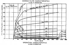
6N6G & Similar
Are nothing more than a high mu triode like a 46 driven into Class A2 by a direct coupled cathode follower. Nothing more, nothing less.
Refer to the 46 Plate Curves, looks like a pentode. To simulate the 6N6G the control grid would be biased up to something like 10V as an operating point by a direct coupled CF.
Worked for me using a 6F6 with G1 & G2 tied together, run in Class A2 driven by paralleled sections of a 6SN7 CF..🙂
The end result looks like a pentode. Unless one looks inside the glass bottle. Or sees no external biasing network.
Attachments
I'm not following you here. There's 9v bias on the top of the cathode resistor and 2v across the tube so 11v going to the supply.
Can you enlarge on what you mean here please?
The polarity marks on the Coleman board are correct.
But the voltage marks on the filament put that at -ve referred to the grid which is on ground.🙂
LED Biasing
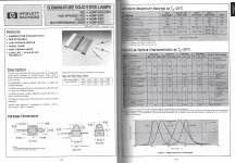
Many common LEDs such as the HLMP 6000 Series are max'd out at 50 mA If. Not a good idea if the filament current is included in the current thru the LED. But would be OK if only the 30 or other plate current.🙂
Many common LEDs such as the HLMP 6000 Series are max'd out at 50 mA If. Not a good idea if the filament current is included in the current thru the LED. But would be OK if only the 30 or other plate current.🙂
Attachments

The polarity marks on the Coleman board are correct.
But the voltage marks on the filament put that at -ve referred to the grid which is on ground.🙂
Ah! I see you are right. An uncharacteristic slip - not sure how I did that.
There needs to be three measurements of capacity made on a simple transformer. That would be primary to secondary, primary to core & secondary to core. Together they form a delta useful in calculating leakage or interference currents in circuitry. Something never shewn on the schematic.
These numbers are especially useful when connecting OPTs, whether SE or PP. Some low cost PP OPTs primaries measure more capacity to one end than the other. That can create problems in FB amplifiers. But can be balanced with a proper equalizing cap on the other end. A problem for non-FB amps to, there is more capacitive loading on one end than the other. Low rp of triodes manages to overcome most of this.
SE OPTs too have more capacity to the core than the other end. That is why the primary leads are color coded. Red usually to the B+.
Somewhere here there is quite a bit of data on this from measurements I did just after the Earth cooled. Might be hard to find tho. Given time I'll do more.🙂
jhstewart9: I measured capacitance on a new out of the box transformer identical to the one I am using for the filament transformer. From primary to secondary it is 36 pF, primary to core and secondary to core varied depending on where I clipped the leads onto the transformer core. These measurements were between 59-81 pF. The measurements were done with the clip lead to the core attached in different holes through the laminations in the core. I tried measuring the connected transformer, but the numbers didn't make sense.
Last edited:
Many common LEDs such as the HLMP 6000 Series are max'd out at 50 mA If. Not a good idea if the filament current is included in the current thru the LED. But would be OK if only the 30 or other plate current.🙂
jhstewart9. I'm not sure how the filament current is involved when biasing with LEDs.
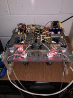
I removed the resistor and its capacitor bypass on the cathode and tried 3 regular 5mm red LEDs in series per side for 5.1 volts of bias on the 30 tubes. See the attached photo. The LEDs resulted in the least noise at the speakers so far. I listened to the amp for about an hour after the swap, and put the resistor and capacitor back in at the end of it. The amp lost most of the qualities that I really like about it with the LEDs in it. With the resistor and capacitor back in, those qualities returned. The sense of having a real musician playing in front of me returned.
During the testing of the 30/6P15P-EV amp, I did a substantial amount of comparative listening with the other amps in my stable. This entails switching the input and speaker cables between two amps, which takes under a minute, and then listening to the dozen or so songs that I always listen to when testing amps. I am very, very familiar with these songs, having used the same ones for a long time. The source is a PC running Tidal (Hifi or Masters), feeding a Musical Fidelity V-90 DAC and then to the amp and to a pair of La Scala speakers. With this setup, the 30/6P15P-EV amp sounds better overall than any other amp in my stable.
Attachments
Ah! I see you are right. An uncharacteristic slip - not sure how I did that.
For clarity, and for anyone looking at this thread in the future, what is the schematic supposed to look like?
Type 30 tube microphonics
The two tubes I currently have in the amp are not microphonic . That said, I did quickly pick two of the least microphonic tubes that I had. I went through about a dozen of the 35 or so tubes I have to find two that are not microphonic at all. While going through the process of filtering tubes, I kept aside the pair that were the most microphonic of the dozen or so I tested and put them in the amp to test them. Any tapping or movement of the chassis makes these tubes ring. Listening at high volume (higher than I would normally listen) and pausing play left a faint ringing in one channel. This ringing followed when the 30 tube was moved to the other channel.
This experiment was done with the amp in a thin wooden frame, and sitting upside down on an unused speaker on the other side of the room, about 14 feet away, from the La Scalas. The photo two posts up shows how the amp is sitting on a thin board on top of a speaker. I think that when the amp is attached to a proper wooden box, some of the microphonic issues will be mitigated. As is, the structure is flimsy and doesn't damp vibration and resonances much. It seems that the tube is also excited into microphonics by being directly affected by sound waves in the air. If I put my mouth close to the tube, and make a loud sound in roughly the frequency of the ringing, I can get the tube to ring lightly.
A solution that would allow for the vast majority of 30 tubes to be used without worries about microphonics would entail a vibrationally isolated socket for the 30s, slack wiring to the socket, and a barrier to sound waves around the 30 tube. The 30 tube gets barely warm in use, so this opens up the possibility of a variety of enclosures that would block the tube from airborne vibration without concerns about overheating. I like the idea of an isolated socket and a glass cover that sits on the chassis to block the tube from airborne vibrations. An inverted glass of the right size and shape should work well enough, and could look nice.
For clarity, and for anyone looking at this thread in the future, what is the schematic supposed to look like?
Here's the corrected version.... I've shown a resistor loading, but I would be using a plate choke of around 150H, like a Lundahl LL1667/8
Attachments

jhstewart9: I measured capacitance on a new out of the box transformer identical to the one I am using for the filament transformer. From primary to secondary it is 36 pF, primary to core and secondary to core varied depending on where I clipped the leads onto the transformer core. These measurements were between 59-81 pF. The measurements were done with the clip lead to the core attached in different holes through the laminations in the core. I tried measuring the connected transformer, but the numbers didn't make sense.
Those numbers look reasonable. As a point of comparison, I measured Pri to Sec 150 pF, Pri to Core 50 pF & Sec to Core 50 pF on a Hammond 1618 OPT. From my olde files, about 50 yrs ago. Hammond seems to be building their transformers & chokes smaller now. I have two of 271X PTs here, they are not the same size at all. So capacities measured today may not be in agreement with those of several years ago.
When many would take these capacities as insignificant as a path for interference, the interference spectrum in today's power systems contains a broad spectrum of harmonice caused by the myriad of switched mode devices we now use. 60 or more years ago flourecent lights were probably the only thing in the home that was a problem. But now we have an entire house full of devices that degrade power quality.
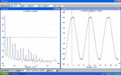
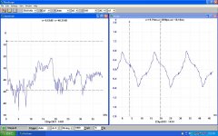
I measured the power spectrum here yesterday, we can see many higher order components. The higher the frequency, the easier to pass thru a small cap.
On the common mode measurement much interference appears. Notice the small glitcth on the 'o' marker, 3.7 mS on the spectrum display. That is caused by a large load somewhere on the system modulating the voltage. These are the kind of things that can get thru a common PT as common mode problem. A Faraday shield would eliminate most of that.
All this not usually a problem on an ordinary amplifier. But when the interference spectrum has an easy path into the cathode on a voltage amplifier, great care must be taken.
There is a large selection of test equipment on the market to measure these problems. The companies I worked for offering such test equipment were HP, R&S, Schaffner, Voltech, Keytek, Aeroflex, IFR & on & on. Other names in the industry would be Dranetz, BMI & many others.🙂
Attachments
Last edited:
Here's the corrected version.... I've shown a resistor loading, but I would be using a plate choke of around 150H, like a Lundahl LL1667/8
Thanks Andy!
jhstewart9. I'm not sure how the filament current is involved when biasing with LEDs.
I removed the resistor and its capacitor bypass on the cathode and tried 3 regular 5mm red LEDs in series per side for 5.1 volts of bias on the 30 tubes. See the attached photo. The LEDs resulted in the least noise at the speakers so far. I listened to the amp for about an hour after the swap, and put the resistor and capacitor back in at the end of it. The amp lost most of the qualities that I really like about it with the LEDs in it. With the resistor and capacitor back in, those qualities returned. The sense of having a real musician playing in front of me returned.
During the testing of the 30/6P15P-EV amp, I did a substantial amount of comparative listening with the other amps in my stable. This entails switching the input and speaker cables between two amps, which takes under a minute, and then listening to the dozen or so songs that I always listen to when testing amps. I am very, very familiar with these songs, having used the same ones for a long time. The source is a PC running Tidal (Hifi or Masters), feeding a Musical Fidelity V-90 DAC and then to the amp and to a pair of La Scala speakers. With this setup, the 30/6P15P-EV amp sounds better overall than any other amp in my stable.
The LEDs form a voltage drop to provide the -ve bias to the 30 Grid, same as the normal 150R. But your numbers look ominous, did you ensure the 30 filament was still 2V? The lower bias measured indicates some of the filament supply voltage is lost!!😱
The LEDs are gone now, but when they were in the amp the filament dropped to 1.8 and 1.9 volts on the two 30s from the 2 volts on it with the resistor and cap.
At the moment the amp is running the power tubes at 28.6 mA and the dissipation is 9.2 watts. This low operating point was in order to accommodate the very small OPTs that the amp was originally built with. The output transformer in this amp now is 12.8K to 8 Ohms. Normally this output transformer is used with a 6P15P-EV that is run at 13+ watts of dissipation and at 47.5 mA or so per tube. The tubes don’t last as long run this way, but they are cheap, and are supposed to sound best when run hot. I am going to try this and listen. After this, I am going to stop working on the amp, and start integrating it as the treble amp in my two way speaker system.
I have been listening to the amp with 220 Ohm cathode resistors on the 6P15P-EV power tubes for a few hours now. With these resistors installed the plate to cathode voltage is 298.5 volts, with 8.82 across the cathode resistor. That is a dissipation of 12 watts and current draw of 40.1 mA per tube. I also tried using a 5V4 in place of the 5Y3, which brought plate to cathode voltage up to 326 volts with 8.7 volts across the cathode resistor. This is 12.9 watts and 39.6 mA of current draw.
The amp doesn’t sound as good when the power tubes are run hotter. Midrange and treble sound more harsh, and the sound seems less coherent. The 5V4 sounds worse in the amp. It was more coherent and real sounding with the 350 Ohm resistors in place. I will return to the 350 Ohm cathode resistors, but I want to listen a bit more to confirm my observations. While the overall sound isn’t as good with the higher dissipation, the bass seems better. It seems tighter and louder in the mix. However, for my ultimate use as a treble amp, the bass performance is mostly irrelevant.
Perhaps I will try a cathode resistor of around 270 Ohms first to hear if it sounds better than the 220 Ohm resistor currently in it.
I had a 5-6 hour listening session last night with the 350 Obm resistors in. The amp sounds fantastic, with plenty of wow moments throughout the listening session. I’m digging it.
If you're not yet using DC Link capacitors as cathode bypasses, I strongly recommend you order a pair. I'm using Vishay and Kemet 40uF. Vishay gives slightly better treble, Kemets have a slightly richer midrange. WIMA and Epcos also make them. I'm pretty sure you'll hear an increase in clarity over electrolytics or other polypropylenes. I'm also using a 15uF DC Link as the last capacitor in the PSU. That makes a difference too.
andyjevans: I’ll order some on the next Digikey order. Is there a particular sku I should be looking for? At the moment the amp has Elna Silmic II on the 30 cathodes. The power supply is split at the final node for the 30s, and the last capacitors are 2.2 uF film caps. I do this on all amps for the final node to the driver tubes.
Last edited:
- Home
- Amplifiers
- Tubes / Valves
- DHT driver for triode wired SE EL84, 6V6 or EL34