Proportions being what they are in the case of high sensitivity speakers, a super quiet amp is an absolute requirement. This is my only build ever where a noise issue was such a problem. jhstewart has the amp and is testing it. He believes that there may be an issue with the HV power transformer that is coupling noise into the circuit. When I get the amp back, I will swap the PT for another one.
With respect to distortion below .1 watts in Stereophile reviews, check out the measurements section that is normally done by John Atkinson. The THD vs output graphs go down to .1 watt. If you extrapolate the line of the graph below .1 watts the results are not promising for many amplifiers, especially PP amps.
With respect to distortion below .1 watts in Stereophile reviews, check out the measurements section that is normally done by John Atkinson. The THD vs output graphs go down to .1 watt. If you extrapolate the line of the graph below .1 watts the results are not promising for many amplifiers, especially PP amps.
This started out as a question about DHT drivers, and triode strapped output tubes, right?
If you want low hum and low noise, I recommend the DHT driver filament has an extremely clean DC supply, and no external rectifier ground loops of such a supply.
0.1 Watt, and lower power out almost certainly requires that.
Push pull amplifiers have to be very carefully designed to reduce crossover distortion.
The design should take care of almost all of the crossover distortion, even before the negative feedback is applied.
Single ended is much simpler, and as previously stated, most designs [good designs] do not have crossover distortion at low to moderate signal levels.
Last edited:
Why do single ended amps sound so good? Has this question been adequately answered yet? If not, it’s probably because hardly anyone is paying attention to what is going on below .1 watts. Stereophile certainly isn’t measuring there, and pretty much no one else is either. It’s always the same endless analysis of what is happening at 1 or 10 or 100 watts while most of the music actually happens well below .1 watt.
Jhstewart9...earlier you wrote:
A good estimate of DF can be made using Rl / rp, so the 6N6G DF would be about 7/24 or ~0.29. Very much like a pentode without NFB. The final DF is a bit less due to OPT resistances, Etc.
A very good description of the 6B5 & the equivalent 6N6G is given on the 6B5 Triadyne data sheet. Plate curves very much like any common power pentode are given on p6 & p8. The plate resistance can be lowered to give better DF by connecting plates one & two together. But then there is less power as is the case when plate & screen of a pentode are connected together.
A bench tested example of a composite tube such as the 6B5 is attached. The 6B5/6N6G can be run in UL too.''
I am grateful to you for the input, in that case you should treat it like any other pentode. It is too much work for me.
Regards
If you want low hum and low noise, I recommend the DHT driver filament has an extremely clean DC supply, and no external rectifier ground loops of such a supply.
I use a DC supply with choke which goes to a Rod Coleman reg. This is particularly important with filament bias where the filament is in the signal path. Others omit the choke, but i include one. The DC supply is floating and only grounded through the cathode resistor.
You've mentioned the possibility of connecting the input section plate of the 6N6G to an UL tap. My current OT is not UL but I did order some Edcors, which are UL, so I will certainly try that when they arrive. Unfortunately, that will be a while since Edcor apparently doesn't keep any product in stock.A good estimate of DF can be made using Rl / rp, so the 6N6G DF would be about 7/24 or ~0.29. Very much like a pentode without NFB. The final DF is a bit less due to OPT resistances, Etc.
A very good description of the 6B5 & the equivalent 6N6G is given on the 6B5 Triadyne data sheet. Plate curves very much like any common power pentode are given on p6 & p8. The plate resistance can be lowered to give better DF by connecting plates one & two together. But then there is less power as is the case when plate & screen of a pentode are connected together.😱
A bench tested example of a composite tube such as the 6B5 is attached. The 6B5/6N6G can be run in UL too.😀
I'm not sure how closely the tubes in your test replicate the characteristics of the 6N6G, which contains two triodes. The combination of tubes I've heard mentioned as being used to replicate the 6N6G are the 76 and 6AC5, both of which are triodes. While the 6F6, used in your test, is a pentode. Perhaps there is a technical explanation for why a combination of a triode and a pentode would mimic the combination of two triodes.
I have not added any NFB to my current 26 - 6N6G SET. I have nothing to measure with but my ears but the bass is tight and well defined, which is what I listen for when I'm considering the need for NFB.
I don't listen to a lot of really bass heavy music, but when I listened to a Thievery Corporation CD that has some punchy electronic kick drum and pretty low and thumpy synth bass on it, the sound is totally solid.
No doubt other genres would provide more extreme tests, but I'm mostly into Americana and Jazz. Both bass guitar and upright bass sound fantastic, natural, detailed and well controlled. Real, acoustic, drum kits sound fantastic. So that's good enough for me, whatever the measurements might be.
And, just to be clear, I'm not someone who believes that NFB should never be used. When I built a PP 6N6G amp last year, using a Magnavox 6V6 chassis and transformers, I did add a bit of NFB. I also added a bit to another Magnavox I modded that uses PP 4P1Ls running in pentode. All of this done by ear, so totally un-scientifically.
FlaCharlie: While the 6N6G is one tube, it does have two elements in it. How does it differ from having two tubes to replace it? Don’t a driver tube and a 6N6G effectively constitute a three stage amp?
andyjevans,
Choke input filter. Good!
A choke input supply has lower transient current than a cap input supply.
And the nature of choke input supply transients has a natural fall off of the high frequencies (such as can cause ground loop transients).
A cap input supply has a flater high frequency nature to the transient (watch out for those ground loop transients).
I seem to remember a noisy amp on the Tubes / Valves threads that had a floating DC supply that powered the Coleman regulator.
A filament winding of a separate filament transformer can pass mains power noise (even noise from the other device such as the B+ winding of the amplifier.
And a single transformer that has B+ and filament windings can do the same - pass noise from one winding to the other.
If a DC supply is floating, and the Coleman regulator is floating, and the Direct Heated filament is floating, that noise can be amplified by that stage.
It is often desired by some to not use a bypass cap to ground across the self bias resistor.
But that allows the noise to be injected into the filament (that 'acts' as a cathode).
A bypass cap shunts that noise to ground.
A bypass cap increases the gain of the stage, but if a cap is used, the gain can be reduced
by changing other circuitry around that tube stage, a divider to the input grid, different plate load, etc.
Perhaps that is why some prefer to use an LED or Diode(s) instead of a self bias resistor.
The LED or Diode(s) impedance is lower than the self bias resistor, so a bypass cap is not needed.
And that lower impedance shunts more of the floating DC filament supply noise to ground.
I prefer to use another solution, no DHT input tube, instead an indirect heated triode, and use a self bias resistor and bypass cap from the cathode to ground.
Last edited:
6A3sUMMER: What you describe in post #448 appears to be exactly what happened with my 30/6P15P-EV amp. Adding a capacitor across the 30’s bias resistor greatly reduced the buzzy hum problem the amp had. You say that an LED or diode has a lower impedance, shunts floating DC filament noise to ground, and will allow the stage to be biased without the need for a bypass capacitor across the self bias resistor. How do other biasing methods fare in this respect? For example, would a constant current sink or a battery based bias also shunt the floating DC filament noise to ground?
tizman,
1. A constant current sink from the filament-"cathode" or cathode to ground would present such a high impedance, that the tube gain would be severely reduced, and the floating supply noise would not be reduced at all . . . unless you bypass the constant current sink to ground with a capacitor.
2. Battery bias in the filament/"cathode" or cathode to ground will be fairly low impedance.
However, you will be constantly charging the battery. Its voltage will increase, the impedance will go up. Depending on the battery type and tube current, it may destroy the battery. For most all applications that is not good.
3. A battery in series with the grid stopper resistor is a better solution for battery bias.
Or, a fixed/adjustable bias supply to the grid circuit (like is more often used in output stages).
Then, the filament supply can be grounded, shunting the filament supply noise to ground (the noise that was there before, because the filament supply was floating).
Last edited:
6A3sUMMER: I will try using LEDs to bias the 30 tubes. I believe that the Coleman regulators are not supposed to be grounded. Another option would be to use the Coleman regulators with filament bias. I’m not sure if that would result in a reduction of noise though.
Yes, it's a dual triode, so technically it is a 3 stage amp using two tubes. Although one stage is not an amplification stage, it's a cathode follower, if that matters.FlaCharlie: While the 6N6G is one tube, it does have two elements in it. How does it differ from having two tubes to replace it? Don’t a driver tube and a 6N6G effectively constitute a three stage amp?
The advantage is that the 6N6G is so easy to implement since the two triodes are directly coupled internally and the bias resistor is also internal, so you just connect the cathode pin directly to ground and feed it the appropriate voltage, which is not particularly high. And the same power supply section can be used for both the input plate and output plate, which further simplifies things.
The low drive requirement allows it to be used very effectively with any of the DHT input tubes we've been discussing.
And, if power output is a factor, it has a higher power output, at lower (5%) distortion, than any of the alternative tubes we've discussed here when they are also used in triode.
While they are not extremely common, neither are they hard to find - there are always some listed online. I've never paid more that $25 shipped for NOS and, if you're patient, they can often be found for much less.
And it sounds great, to my ears. Especially with a DHT as input.
While some people may be philosophically opposed to using more than two stages, I'm more concerned with results. Philosophically, I value simplicity and this is no more complex, and in some ways easier to implement, than a traditional two stage design.
Much of the extremely detailed data sheet is over my head, but if you haven't looked at it already, here it is:
https://tube-data.com/sheets/201/6/6B5.pdf
Obviously, there are other choices and you may prefer them for whatever reason. But the 6N6G certainly merits serious consideration.
Last edited:
tizman,
I am pretty sure that Rod Coleman can tell you what is the best way to apply the Coleman regulator for your type 30 tubes, and your amplifier.
He is a regular poster on this forum.
There may also be some good application information at his web site.
I am pretty sure that Rod Coleman can tell you what is the best way to apply the Coleman regulator for your type 30 tubes, and your amplifier.
He is a regular poster on this forum.
There may also be some good application information at his web site.
FlaCharlie: I am in the process of sourcing a few to try them out. For clarity, you use a DHT, then triode 1 of the 6N6G is the cathode follower, and triode 2 is the power triode? Is the 6N6G internally constructed so that it is set up as a cathode follower followed by the power triode? I’ll have a closer look at the data sheet as well. A three stage with a 30 followed by a triode connected 6P15P-EV, and then followed by a big triode or triode wired pentode could be fantastic if the qualities of the first two stages can make it through the last stage to the speakers.
tizman,
I am pretty sure that Rod Coleman can tell you what is the best way to apply the Coleman regulator for your type 30 tubes, and your amplifier.
He is a regular poster on this forum.
There may also be some good application information at his web site.
Rod Coleman has been very helpful. I have asked for, and received, help from him on multiple occasions. I feel like I’m annoying him with my many questions. There is information on the filament biasing of many tubes on his site, on Bartola Valves and on DIY Audio, but nothing for the type 30. The problem I am having with my amp may have been masked by adding a capacitor across the 30’s cathode bias resistor, but it is still there in reality. Ideally, I would fix the problem so that there is no need for the cathode bypass capacitor as I prefer a simple cathode resistor.
The DHT connects to the grid of the 6N6G, just like it does to the grid of the 6BQ5 or 6V6 in your current amp. The input triode is the cathode follower, the output section is the power triode.FlaCharlie: I am in the process of sourcing a few to try them out. For clarity, you use a DHT, then triode 1 of the 6N6G is the cathode follower, and triode 2 is the power triode? Is the 6N6G internally constructed so that it is set up as a cathode follower followed by the power triode?
The 6N6G can be dropped into the same socket as a 6V6. The heaters are still on Pins 2 and 7. The grid is still on Pin 5. The output plate is still on Pin 3, so that connection doesn't change either.
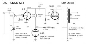
Here's the schematic of my amp, in it's current configuration:
Attachments

6A3sUMMER: I will try using LEDs to bias the 30 tubes. I believe that the Coleman regulators are not supposed to be grounded. Another option would be to use the Coleman regulators with filament bias. I’m not sure if that would result in a reduction of noise though.
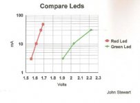
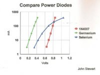
In general silicon diodes have lower impedance & drop than any color of LED. And Germanium diodes even lower. The lowest drop LEDs begin at the red end of the spectrum & as we advance thru orange, yellow, green & so on the forward drop increases. There is also the IRED, infra red emitting diode.
The important spec for this application is the dynamic resistance at the operating current. The dynamic resistance is not E / I. It is delta E / delta I at the operating current. Need to read the data sheet carefully.
As an aside some of the guys at the HP SS lab constructed a balanced mixer using red LEDs instead of Shottky's. That can be used for a number of purpose such as a double sideband suppressed carrier signal. A starting point for a sideband transmitter. Matched sets of four Scottky's were sold for apps such as ring modulators & mixers.
We sold those LEDs by the million, the prices dropped like a rock!
LEDs & small signal diodes LEDs became a commodity & that part of HP was sold off to Avago Technologies.
Attachments
My report on the composite tube in #437 is simplified somewhat. The objective was to simply shew what is possible. So the calcs of rp & so on are on the rough side & could be improved a lot. The hookup worked, I left it at that.The Sylvania 6N6G data sheet shews much better what is happening inside the tube. Notice the power section is actually drawn as a pentode. And grids one & two are both driven by the intermal CF, same as my bench tested example.🙂
All part of the hobby, look a little father than the noise the cct can make. And look at the noise closely too!😱
All part of the hobby, look a little father than the noise the cct can make. And look at the noise closely too!😱
Attachments
The DHT connects to the grid of the 6N6G, just like it does to the grid of the 6BQ5 or 6V6 in your current amp. The input triode is the cathode follower, the output section is the power triode.
The 6N6G can be dropped into the same socket as a 6V6. The heaters are still on Pins 2 and 7. The grid is still on Pin 5. The output plate is still on Pin 3, so that connection doesn't change either.
Here's the schematic of my amp, in it's current configuration:
FlaCharlie: Looks great. Thanks for the schematic.
My report on the composite tube in #437 is simplified somewhat. The objective was to simply shew what is possible. So the calcs of rp & so on are on the rough side & could be improved a lot. The hookup worked, I left it at that.The Sylvania 6N6G data sheet shews much better what is happening inside the tube. Notice the power section is actually drawn as a pentode. And grids one & two are both driven by the intermal CF, same as my bench tested example.🙂
All part of the hobby, look a little father than the noise the cct can make. And look at the noise closely too!😱
Is the 6N6G operated as a tetrode in FlaCharlie’s schematic attached above? As drawn by FlaCharlie, the power element looks like a triode. In the data sheet the power element has a second grid connected to the first grid and to the cathode. On the 6N6G power element, what is the part of the tube that looks like another grid element between the two connected grids and the cathode?
- Home
- Amplifiers
- Tubes / Valves
- DHT driver for triode wired SE EL84, 6V6 or EL34