Thanks Rod. It’s the one that I vaguely remember from the past. I couldn’t open it yesterday when I clicked on it while on their site. So suppressor grid and cathode disconnected, and G2 dissipation is listed as 1.5 watts instead of 2 watts in the EL84 are two obvious differences. I did some reading last night, and Wavebourn said in past postings that the data sheets likely reflect the listed hourly ratings. So a tube that is rated for 10000 hours will show more conservative maximum values that are likely to allow it to reach the hour rating. He did say that on close inspection of 6P14P-EV and 6P15P-EV innards, G2 has a different construction. This is a quote from one of his posts...
“You can't use 6P15P in ultra-linear amp designed for EL84 tubes. Screen grid is denser, and if to apply the same voltage as to the EL84's screen grid, it's current will be too high. 6P15P was designed for more linear mode in video amps with higher voltage swing on anode, that's why the difference. When I did not know what exactly was different, I thought that it is the same tube specified for more linear operations, but surgical experiments confirmed that screen grids are different, so in pentode mode voltage on the 2'nd (screen) grid must be lower than for EL84 tube.”
It’s a really great sounding tube and cheap as chips.
Last edited:
hello Tiz,
Here's a composite 6П15П data-sheet, including the «tough» EV & V varieties, courtesty of tubes.ru
Looks very similar to the 6BQ5 with the exception of the pinout. The 3rd vers appears to be a premium type.
Thanks Rod. It’s the one that I vaguely remember from the past. I couldn’t open it yesterday when I clicked on it while on their site. So suppressor grid and cathode disconnected, and G2 dissipation is listed as 1.5 watts instead of 2 watts in the EL84 are two obvious differences. I did some reading last night, and Wavebourn said in past postings that the data sheets likely reflect the listed hourly ratings. So a tube that is rated for 10000 hours will show more conservative maximum values that are likely to allow it to reach the hour rating. He did say that on close inspection of 6P14P-EV and 6P15P-EV innards, G2 has a different construction. This is a quote from one of his posts...
“You can't use 6P15P in ultra-linear amp designed for EL84 tubes. Screen grid is denser, and if to apply the same voltage as to the EL84's screen grid, it's current will be too high. 6P15P was designed for more linear mode in video amps with higher voltage swing on anode, that's why the difference. When I did not know what exactly was different, I thought that it is the same tube specified for more linear operations, but surgical experiments confirmed that screen grids are different, so in pentode mode voltage on the 2'nd (screen) grid must be lower than for EL84 tube.”
It’s a really great sounding tube and cheap as chips.
Well yes, that's true. It's not just the g2 power rating but also the g2 current it draws is more than 6P14P at given anode and g2 voltages and the same anode current (different bias of course).
In triode mode tough, the 6P15P has more gm and is more linear.
In triode mode tough, the 6P15P has more gm and is more linear.
As linear as a DHT?
As linear as a DHT?
Well no, but it's a good enough to build a well performing amp.
I've spent a year using DHTs to drive indirectly heated outputs of higher mu, like 17. It's true that the EL84 and equivalents are a good choice, but EL33 is better sounding still. For higher power the EL38 is the star of the show. Anode top cap if you can deal with that and like EL33 it needs at least 5K primary, even 6.6K in SE. Not DHTs but getting closer - they're very good. The EL33 and EL38 are more common in Europe.
I've spent a year using DHTs to drive indirectly heated outputs of higher mu, like 17. It's true that the EL84 and equivalents are a good choice, but EL33 is better sounding still. For higher power the EL38 is the star of the show. Anode top cap if you can deal with that and like EL33 it needs at least 5K primary, even 6.6K in SE. Not DHTs but getting closer - they're very good. The EL33 and EL38 are more common in Europe.
Did you,by any chance, have the opportunity to work with EL12 Spezial?
Did you,by any chance, have the opportunity to work with EL12 Spezial?
I tried EL12, EL12n, EL12Spez and EL38. EL38 was the best of them. If you can't deal with an anode top cap, the EL12n is a good cheap alternative and around 1K Ri so easier to match up to OPTs. These are all good outputs - 18W dissipation or more. The EL38 is well priced in Europe and not too rare. Quite a lot of Mullards were made.
.
Last edited:
Thanks for the update, Andy. Could you please share some details / operating points?I tried EL12, EL12n, EL12Spez and EL38. EL38 was the best of them. If you can't deal with an anode top cap, the EL12n is a good cheap alternative and around 1K Ri so easier to match up to OPTs. These are all good outputs - 18W dissipation or more. The EL38 is well priced in Europe and not too rare. Quite a lot of Mullards were made.
So, are you running the EL38 in pentode or triode? What's the OT primary? How much power output are you getting?
I assume you're using it in a 2-stage amp. Which DHTs have you used with it?
Thanks for the update, Andy. Could you please share some details / operating points? So, are you running the EL38 in pentode or triode? What's the OT primary? How much power output are you getting? I assume you're using it in a 2-stage amp. Which DHTs have you used with it?
EL38 is in triode with an O-Netics 3.5K OPT on the 4 ohm setting. Haven't measured power out. Dissipation is around 18W, 260v a-k at 70mA. Yes - 2 stage amp as usual for me. The 10Y was great as a driver but I also used EL33 which was pretty good too. I imagine a 2P29L would be a nice driver, though I didn't try it.
.
Last edited:
I assume your speakers are nominally 8 ohms, correct? If so, that would present a 7k load to the tube.EL38 is in triode with an O-Netics 3.5K OPT on the 4 ohm setting. Haven't measured power out. Dissipation is around 18W, 260v a-k at 70mA. Yes - 2 stage amp as usual for me. The 10Y was great as a driver but I also used EL33 which was pretty good too. I imagine a 2P29L would be a nice driver, though I didn't try it.
There don't seem to be any curves for these, much less triode curves. How much negative voltage do you have on the grid? Are you using cathode bias? If so, what value resistor?
Any thoughts on using drivers such as 26 or 01A?
Yes, speakers Alpair 10M are nominally 8R. Curves here. I think you need a bit more current than the 01A and 26, though I did use 01A for a while before going back to 10Y. A cathode follower or source follower is often used with the 01A but I never rigged it up. Cathode bias -11v, 156R resistor 3W. DC Link cathode bypass (40uF) on all my amps these days - they've kicked out everything else, love them. Vishay or Kemet.
Attachments
Thanks, Andy. Did you try connecting your speakers to the 8 ohm tap of the OT, assuming it has one?Yes, speakers Alpair 10M are nominally 8R. Curves here. I think you need a bit more current than the 01A and 26, though I did use 01A for a while before going back to 10Y. A cathode follower or source follower is often used with the 01A but I never rigged it up. Cathode bias -11v, 156R resistor 3W. DC Link cathode bypass (40uF) on all my amps these days - they've kicked out everything else, love them. Vishay or Kemet.
I ask because the curves specify a 3.1k load for SET operation. You'd be getting a bit more power output using your OT at 3.5k. Power output is listed as 3.6w max, which I assume means at 10% distortion.
So you're probably getting a bit less at an effective 7k primary. Lower distortion, though, and perhaps your speakers just work better like that.
I'm a fan of the DC Links too, although I've never used them as cathode bypasses and I use the Panasonics. The 26 - 6N6G SET I've got breadboarded doesn't use a cathode bypass since the 6N6G cathode pin connects to ground and I'm running battery grid bias on the 26s. I'm using them in the PS though.
Thanks, Andy. Did you try connecting your speakers to the 8 ohm tap of the OT, assuming it has one?
Yes, sounded much better on the 4ohm tap. I prefer a higher primary, which gives me a cleaner sound when I've used it. I use 5K-8K on my 300b outputs. I don't need the power.
A good estimate of DF can be made using Rl / rp, so the 6N6G DF would be about 7/24 or ~0.29. Very much like a pentode without NFB. The final DF is a bit less due to OPT resistances, Etc.
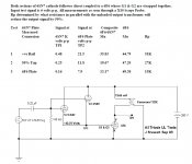
A very good description of the 6B5 & the equivalent 6N6G is given on the 6B5 Triadyne data sheet. Plate curves very much like any common power pentode are given on p6 & p8. The plate resistance can be lowered to give better DF by connecting plates one & two together. But then there is less power as is the case when plate & screen of a pentode are connected together.😱
A bench tested example of a composite tube such as the 6B5 is attached. The 6B5/6N6G can be run in UL too.😀
Attachments
Yes, sounded much better on the 4ohm tap. I prefer a higher primary, which gives me a cleaner sound when I've used it. I use 5K-8K on my 300b outputs. I don't need the power.
This is the very reason why I tried the 9K to 6 Ohm Decware OPT in the 30/6P15p-EV amp. The obsession with power is the product of decades of low sensitivity speakers and the often terrible mass market high wattage amps that go with them. What is the THD at one watt or at 100 watts? Who cares? I want to see THD at .00001 to .001 watts. That’s where the magic happens.
Stereophile shows distortion down to .1 watts in their full amplifier reviews. At .1 watts, with my speakers in my setup, I’m getting 93.4 DB at the listening position. A quick review of the graphs about output vs distortion at 1 KHZ on Stereophile online shows some disturbing trends if you extrapolate below .1 watts with many amps. Single ended amps fare best.
When a power amp has to have low distortion at 0.1 Watt or less, it has to have very low noise and very low hum.
Many distortion meters actually measure fundamental, versus the total of harmonic distortion, plus noise, plus hum.
And if they do not measure it that way, OK, but then the measurement does not show the total effect on how the amplifier sounds at low power.
Also, crossover distortion tends to occur at low wattage.
After all, crossover distortion occurs at the signal voltages that are near to the zero crossings (near 0 Volts).
It is still present at high wattage, but the same low crossover distortion is much smaller than the high wattage output.
It is a factor of proportions (crossover distortion amplitude, versus power output amplitude).
Last edited:
A properly designed single ended amplifier had better not have any crossover distortion at low to moderate signal levels.
Or, it is not worth its weight in salt.
For that amplifier, the only unusual shapes at or near the zero crossings had better not show up, unless the amplifier is grossly overdriven, causing such things as shifting bias voltages, RC coupling grid current bias shifts, negative feedback sticking, and other possible effects.
It hurts to overdrive, do not do that.
- Home
- Amplifiers
- Tubes / Valves
- DHT driver for triode wired SE EL84, 6V6 or EL34