Andy...thank you. Yes you are correct, its a fine tube for DHT drivers.
Tizman...I used C3M as 300B driver. Not enough gain for standard 2 volt input. Please also consider C3g. Regards
Or 5A/152M which is similar to the C3g.
FlaCharlie;6632446 So said:I was using 5A/152, M or G (wire ended), a C3g clone up until very recently, and it works well. Curves are pretty much the same as the C3g. I'm auditioning one or two others I haven't mentioned. I still have D3a and C3g to try out. Plus C3M which doesn't have enough gain in triode. I'm trying to set up some shootouts but it's time consuming and may take a while.
.
Last edited:
Yes, it not that simple, the counting should start backwards.I'm guessing it's not that simple.
Simplified concepts:
Firstly you must choose output tube and output transformer couple (depending of loudspeaker and desired sound pressure, which are roughly determines required power).
This output tube and power determines the grid swing.
The driver swinging capacity should exceed it -for example 120 percent-, and driver output "capacity" (current, impedance, distortion) must serve the output tube grids requisition (swing, current).
If the output tube grid swing requirement -for example- 150Vpp, the two stage amplifier driver tube gain must be at least 150V/5.657V ( max. swing / peek_to_peek of 2V RMS ), i.e. 26.5.
With 20% headroom the required gain is about 32.
If you have tubes with gain 10, the "driver" tube grid swing is 150Vpp/10= 15Vpp + 20% headroom i.e. 18Vpp.
So the driver tube must be capable working with at least 0... -18V grid voltage, and operating point must be middle in this range.
At this operating point the tube anode-cathode voltage must be at least as large as half of the required swing (+ few ten Volts, depending of tubes cutoff voltage), and this tube's B+ must exceed this operating point's voltage+half of the required swing (+ few ten Volts for headroom).
At this operating point the driver tube current and output impedance must have to satisfy to output tube grid requirements (possible A2 mode).
So, if the 10x gain driver is OK, the next step is calculating of VAS (Voltage Amplifying Stage) requirements.
The driver max. grid swing is 18Vpp, so if the VAS tube has 10x gain, the theoretical input swing is 1.8Vpp (more, depending of VAS stage's implementation).
The VAS tube must be capable 18Vpp anode swing if it's grid swinging 1.8Vpp.
The VAS stage must be tolerate 2VRMS input (5.657Vpp) without hard clipping.
The accepted design philosophy:
at overdrive the "rearmost" stage should be clipping rather than gain or driver stages.
Counting backwards is good practic.
However, start with genre of music.
"Girl with guitar" or "Mahler/Shostakovitch symphonies" require different types of amplification.
The former suits SE more; the latter begs for PP.... (not to confuse with output power).
However, start with genre of music.
"Girl with guitar" or "Mahler/Shostakovitch symphonies" require different types of amplification.
The former suits SE more; the latter begs for PP.... (not to confuse with output power).
Andy...thank you. Yes you are correct, its a fine tube for DHT drivers.
Tizman...I used C3M as 300B driver. Not enough gain for standard 2 volt input. Please also consider C3g.
Regards
minjah:I will be using the C3M as a pentode in that amp.
I used split PS before, too, and I understand the theory behind that aspect. I was just wondering if there was any advantage, whether practical or technical, to using such a low cap value.
Logically, it seems to me that doing so could have negative consequences if the small cap can't keep up with the demand. But, since I lack the knowledge and ability to measure, I don't know if that would happen in practice.
I also tend to build stuff with more PS filtration than it probably really needs. While a larger cap (15uf to 50uf) might be overkill in terms of smoothing, I'd rather have more energy storage reserve than I need rather than (possibly) not enough.
I like your cash box amp. I'm always looking for ways to use repurposed elements in my builds.
I’m uncertain about the theory on final cap size as well. I was under the impression that the final node for the driver tubes didn’t require a large cap, as it has a small draw, and that a film cap is preferable on that node, but I cant recall how I got that impression. I need to do some research. If anyone can point me to formula or rule of thumb, that would be great.
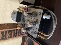
I love building into old metal boxes. I have built four amps this way using the innards of console amps. I gifted two of them and have two still. Attached is a photo of my loctal cash box amp.
Attachments
My general impression is the same, although I can't offer any rule of thumb or documentation.I’m uncertain about the theory on final cap size as well. I was under the impression that the final node for the driver tubes didn’t require a large cap, as it has a small draw, and that a film cap is preferable on that node, but I cant recall how I got that impression. I need to do some research. If anyone can point me to formula or rule of thumb, that would be great.
I just think that 2.2uf, 1.5uf or whatever you're using seems a bit too low a value and I can't think of any reason why a larger value would create a problem.
Again, my concerns are not about how this affects smoothing, it's about how it affects current reserve. As far as I know, PSUD2 sims don't provide any info on that aspect. Of course, I may be mistaken about that since I'm not particularly experienced in the use of PSUD2.
My general impression is the same, although I can't offer any rule of thumb or documentation.
I just think that 2.2uf, 1.5uf or whatever you're using seems a bit too low a value and I can't think of any reason why a larger value would create a problem.
Again, my concerns are not about how this affects smoothing, it's about how it affects current reserve. As far as I know, PSUD2 sims don't provide any info on that aspect. Of course, I may be mistaken about that since I'm not particularly experienced in the use of PSUD2.
I have used PSUDII for years now, but during this build learned a whole lot more about it. It don’t think that the program tells you that directly. In my brief look for info, I didn’t find anything. I’ll have another look. I’m hoping that the final cap on the driver tube’s power supply node can be of small uF and therefore small enough size to use a film cap in that position (positions in my case). I’m going to go with that until I hear or learn otherwise.
minjah:I will be using the C3M as a pentode in that amp.
Ok then. Try triode also and decide which way you prefer.
Tizman and Fla.....2.2uf and 15uf -both are correct. when and where that's the question. I think learning PS for tube amp, se or pp is very important. Nothing like too low/too high -it needs to be as require/as designed for the purpose. Thumb rules are available but that should be dogged out after learning the basics.
Requesting our learned friend to direct us to some good docs/reads on PS please we will be obelized.
Regards
Regards
Obviously, both values have their uses in different situations.Tizman and Fla.....2.2uf and 15uf -both are correct. when and where that's the question. I think learning PS for tube amp, se or pp is very important. Nothing like too low/too high -it needs to be as require/as designed for the purpose. Thumb rules are available but that should be dogged out after learning the basics.
Requesting our learned friend to direct us to some good docs/reads on PS please we will be obelized.
In this particular case we're talking about the value of the PS caps used in tizman's amp to supply the two type 30 input tubes. He posted a schematic earlier, which shows them as being 1.5uf, although he may be using 2.2uf now.
Again, my concern is not related to PS ripple reduction. Let's assume that is adequate whichever value is used. It certainly should be since he has ~600uf earlier in the PS.
But what value will ensure that the input tubes have an adequate current reserve. Clearly, a 15uf (or higher) cap would provide more current reserve than a 1.5uf or 2.2uf.
Perhaps they don't actually need that much, though, I don't know. But, in this case, would having more reserve than necessary be detrimental in any way? If there's no downside, I'd rather have a bit more than is necessary than to possibly not have enough.
Perhaps @jhstewart9 will be able to offer some insight.
Film caps in these higher values are a bit larger but they're not exactly huge.I’m hoping that the final cap on the driver tube’s power supply node can be of small uF and therefore small enough size to use a film cap in that position (positions in my case). I’m going to go with that until I hear or learn otherwise.
Obviously, both values have their uses in different situations.
In this particular case we're talking about the value of the PS caps used in tizman's amp to supply the two type 30 input tubes. He posted a schematic earlier, which shows them as being 1.5uf, although he may be using 2.2uf now.
Again, my concern is not related to PS ripple reduction. Let's assume that is adequate whichever value is used. It certainly should be since he has ~600uf earlier in the PS.
But what value will ensure that the input tubes have an adequate current reserve. Clearly, a 15uf (or higher) cap would provide more current reserve than a 1.5uf or 2.2uf.
Perhaps they don't actually need that much, though, I don't know. But, in this case, would having more reserve than necessary be detrimental in any way? If there's no downside, I'd rather have a bit more than is necessary than to possibly not have enough.
Perhaps @jhstewart9 will be able to offer some insight.
Film caps in these higher values are a bit larger but they're not exactly huge.
FlaCharlie: I’ll put some extra capacitance in parallel and give it a listen. It would be nice to have a clear answer on what is ideal though.
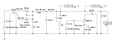
Amplifier Power Supply with ‘Trick’ Final capacitor
Thought I’d seen everything but this is something new. Given the lowest frequency of a Bass Guitar is 80 Hz while Piano & Pipe Organ is much lower, this is a great way to ruin the overall performance of your system. When the PS sags on low frequencies, that causes intermod distortion products to be created on all the other frequencies passing thru the amplifier to the speaker. Some may like that. These trick circuit modifications should come with a disclaimer. Such as ‘Your results may differ’. And if we could find the originator, ask why the feeble final cap improves the performance of the system.
But I’m not the listener, so enjoy. The simulations show the size of the AC voltage modulating the PS B+ by a single triode in the 5998 whens driven to 3.75W at 40 Hz. Two values of the final cap are selected by the Key “Z”. A too small cap in the PS filtering is a leading cause of ‘motor boating’ in amplifiers.🙂
Attachments

Well no, 82.4Hz is E of the guitar. The low E of the bass guitar is 41.2Hz (precisely one octave lower) and 5-string bass B note is just under 31Hz.
Thought I’d seen everything but this is something new. Given the lowest frequency of a Bass Guitar is 80 Hz while Piano & Pipe Organ is much lower, this is a great way to ruin the overall performance of your system. When the PS sags on low frequencies, that causes intermod distortion products to be created on all the other frequencies passing thru the amplifier to the speaker. Some may like that. These trick circuit modifications should come with a disclaimer. Such as ‘Your results may differ’. And if we could find the originator, ask why the feeble final cap improves the performance of the system.
But I’m not the listener, so enjoy. The simulations show the size of the AC voltage modulating the PS B+ by a single triode in the 5998 whens driven to 3.75W at 40 Hz. Two values of the final cap are selected by the Key “Z”. A too small cap in the PS filtering is a leading cause of ‘motor boating’ in amplifiers.🙂
jhstewart: Please explain what the sims are showing, and how this impacts the performance for this amp. There is a big difference in the AC measurement. Does the large current draw of the 5998 triode affect this? In the case of this amp, the power supply is split at the 30 tube. The 30 has a current draw of 3 mA. The small 2.2 uF capacitor is on the driver tube rather than on the power tube as shown in the sims. I understand that the sims are meant to show what happens when cap size is small vs big, but what is the impact of cap size with a much smaller tube with less current draw?
The split of the power supply at the point where it goes to the left and right driver tube is supposed to be an attempt at decoupling the two channels from each other. My understanding is that this is the designers reason for the split. As to the size of the capacitors, the small size may just be their way of saving some money. It is easy enough to increase the amount of capacitance on the driver tubes on this amp, and I will try it soon.
It would be useful to have a guideline that should be followed for sizing the capacitor that feeds a node. In the case of this amp as it set up now, the power tubes draw close to 100 mA. At the power supply node for the power tubes, there is a 100 uF capacitor. As the power supply splits before the nodes for the 30s, each has a 2.2 uF capacitor. Each 30 draws around 3mA. Is it a uF/mA equation? If so, the power tubes have 1 mA/1 uF. The driver tubes draw 3 mA and have 2.2 uF, which is 1 mA:0.7333 uF.
Again, as I have already said, I don’t know how to figure out what constitutes a properly sized capacitor for a given power supply node. I welcome any sources of reading material or methods that can be used to figure this out. I haven’t found any online yet but I may be looking in the wrong place.
Last edited:
For a single-ended amp, the power supply is in series with the load. Maybe just ask yourself what you want to be in series with the load. (And is also quiet enough for the job, etc.)
All good fortune,
Chris
All good fortune,
Chris
For a single-ended amp, the power supply is in series with the load. Maybe just ask yourself what you want to be in series with the load. (And is also quiet enough for the job, etc.)
All good fortune,
Chris
Chris: That is a good question. I recall very spirited threads here, and on other forums, about what a good power supply should be like. There was not very much in the way of hard science and measurements in those threads. People mostly had opinions based upon listening. The tension between listening and measuring was, and is, always present.
Here are some of the things I read:
-I should avoid series resistance as much as possible in a power supply because it kills dynamics. For this reason big H value chokes with low resistance are preferable to resistors to get the same smoothing. A power supply should always have less than 100 Ohms of total series resistance, with 50 Ohms being the target.
I try to keep series resistance to the power tubes low in my amps. This amp has 191 Ohms of series resistance in the power supply before the power tubes. I'm 91 Ohms over the limit.
-Too much capacitance is bad. It bloats the sound.
I don't follow this, and in fact usually go too far in the opposite direction.
-Got to be Black Gates, film caps are not as good and forget about electrolytics.
I have never even seen a Black Gate that was over 16 volts.
-Ideally, every tube should have it's own power supply. When a transformer is shared between stages, or between channels, the stages and channels modulate each other and sound quality suffers. When using a single power transformer for a two channel amp, take every opportunity to decouple stages and channels.
When I build an amp, I do try to decouple. The split of the power supply at the 30's is me trying to decouple the channels from each other. Ignoring the cap size, does the split as implemented in my amp decouple the two channels, or am I wasting my time and effort?
Last edited:
When I build an amp, I do try to decouple. The split of the power supply at the 30's is me trying to decouple the channels from each other. Ignoring the cap size, does the split as implemented in my amp decouple the two channels, or am I wasting my time and effort?
I use a separate PSU for the input section, rather than decoupling channels. No doubt overkill for a 30 tube. It does mean you can design the PSU specifically for a lower voltage/current stage.
I'm pretty sure the "originator" of this is Decware. At least that's the only place I've ever seen such a tiny cap used in that position in a PS. I'm not sure if they use it in any of their other amps besides the little Zen. I actually assumed it was an error in the schematic, but apparently it's a "design feature".Thought I’d seen everything but this is something new. . . . These trick circuit modifications should come with a disclaimer. Such as ‘Your results may differ’. And if we could find the originator, ask why the feeble final cap improves the performance of the system.
I doubt that's why they use them. Considering that the Zen amps sell for anywhere from $1000 to $3000, I doubt their profit margins are so thin that they need to skimp on the value of a PS cap.As to the size of the capacitors, the small size may just be their way of saving some money.
When I looked at the schematic and pics of the Zen a while back I couldn't help but notice that it's essentially the same as the little Magnavox amps that came in their cheaper line of console stereos.
I read somewhere that Decware once admitted that the Zen was essentially a copy of a similar Zenith console stereo amp. The Magnavox and the Zenith can often be found for under $50 if you're lucky enough to find a derelict console locally, or for $100 or so if you buy one on eBay.
The tiny cap is not copied from the Zenith, however. Zenith uses a 20uf cap to supply the input tube.
Last edited:
I use a separate PSU for the input section, rather than decoupling channels. No doubt overkill for a 30 tube. It does mean you can design the PSU specifically for a lower voltage/current stage.
Is it really overkill though? In your experience, does using a separate power supply for the input tube result in better sonics? If so, is it the elimination of modulation of the input by the output section through the common core of the transformer the reason for these better sonics, or is it something else?
Your novel construction method lends itself to splitting input and power sections, and mixing and matching them. I have been thinking about how to break amps up into sections for a while now, and have not come up with anything that works and is also aesthetically pleasing. Once I work through some of the chassis and top plates I have at hand I will pursue your method. Thanks!
I'm pretty sure the "originator" of this is Decware. At least that's the only place I've ever seen such a tiny cap used in that position in a PS. I'm not sure if they use it in any of their other amps besides the little Zen. I actually assumed it was an error in the schematic, but apparently it's a "design feature".
I doubt that's why they use them. Considering that the Zen amps sell for anywhere from $1000 to $3000, I doubt their profit margins are so thin that they need to skimp on the value of a PS cap.
When I looked at the schematic and pics of the Zen a while back I couldn't help but notice that it's essentially the same as the little Magnavox amps that came in their cheaper line of console stereos.
I read somewhere that Decware once admitted that the Zen was essentially a copy of a similar Zenith console stereo amp. The Magnavox and the Zenith can often be found for under $50 if you're lucky enough to find a derelict console locally, or for $100 or so if you buy one on eBay.
The tiny cap is not copied from the Zenith, however. Zenith uses a 20uf cap to supply the input tube.
FlaCharlie: Yes, if’s Decware. I don’t know if they still do it in their Zen amps, but they have done it for a very long time. I’ve heard about the Magnavox thing as well, but weren’t most of the Magnavox amps pentode connected when they were single ended?
If you have not seen it, check out Stereophile’s Decware Zen amp review in the March 2021 issue. It’s available free online. It’s a very good review.
Buying old console and organ amps and putting their guts into a new chassis is something I did many times in the past, and I still have a dozen or so console and organ amp chassis on hand that I could convert. The final results varied, as many consoles had very small OPTs. The first amp I ever built that way was a Decware Zen clone built out of the innards of a Magnavox console amp with chunky OPTs. That amp sounded great. I sold it awhile back to a guy who still uses it as a mid/treble amp in a big DIY two way speaker.
- Home
- Amplifiers
- Tubes / Valves
- DHT driver for triode wired SE EL84, 6V6 or EL34