I changed something when I took the HV PT off the chassis. I put the PT back on last night and returned the amp to its original condition in which the hum was just audible when no music was on. Unfortunately the louder hum of when the PT was removed remained. This tells me that I broke or changed something that caused the increase in hum. I will get a photo of the entire amp bottom when I get back to it tonight.
Part of me is wondering if you're just expecting too much from the 30 in terms of hum.
When you say the hum was quiet but still audible, if that was at idle with no music playing, it might be as good as can be expected from a 30. After all, the 30 does have a reputation for having more hum than some of the other DHTs.
Obviously, if it was audible with music playing, that's not acceptable.
Also, it might be helpful if you could post a pic of the entire under-chassis area. There may be something about the overall layout that's influencing the hum.
Just to rule out any issues with the filament supply, I would suggest you temporarily try to heat the tube with a battery which is, of course, what it was designed to use.
The filament is 2v and only .06a. A single AA battery will give you 1.5v and starving the filaments tends to help too.
I was under the impression that most DHTs could be implemented as hum free. With the 30 and a 6V6 in my amp, the hum was very quiet, but the gain not quite sufficient. With a 30 and an EL84, the hum was audible between tracks, and the gain was sufficient.
I hope that with proper implementation I can get the 30 hum free. I probably need to have separate power supply and circuit chassis, or at least be much more careful with wiring and layout. If the 30 is not going to ever be hum free due to its innate qualities, I really don’t want to bother building an entire two chassis amp to find out. Breadboarding first would appear to be of little use as any breadboard I can put together is going to generate far more hum than even a mediocre amp built into a chassis.
I will get a photo of the full underside as is, and then try battery filaments later this evening.
DC Powered filaments:
1. There are lots of rechargeable Lead Acid Gell Cells available, they are 2V.
2. Ignore the following if you are using a well regulated 2.0V DC filament supply for the 30.
AC powered filaments:
How did you implement the hum balance pot and rest of the 2.0VAC filament circuit?
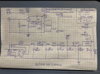
Please post a schematic of the complete filament supply.
It looks like you have parallel series dropping resistors to one side of the filament, but not to the other side of the filament.
You need 1.0VAC from ground to one side of the filament, and 1.0VAC of the opposite phase to the other side of the filament, and the center of those filament voltages need to reference equally to ground.
Since the filament "is" also the "cathode", it takes careful design of the AC filament power circuitry.
How many type 30 tubes do you have to try?
This is important.
I will explain if you wish.
You noticed that the gain with the 6V6 was lower than the gain of the EL84.
And, that the hum was lower with the 6V6 than with the EL84.
That is correct, a constant hum from a type 30, will be quieter when the output tube gain is lower.
1. There are lots of rechargeable Lead Acid Gell Cells available, they are 2V.
2. Ignore the following if you are using a well regulated 2.0V DC filament supply for the 30.
AC powered filaments:
How did you implement the hum balance pot and rest of the 2.0VAC filament circuit?
Please post a schematic of the complete filament supply.
It looks like you have parallel series dropping resistors to one side of the filament, but not to the other side of the filament.
You need 1.0VAC from ground to one side of the filament, and 1.0VAC of the opposite phase to the other side of the filament, and the center of those filament voltages need to reference equally to ground.
Since the filament "is" also the "cathode", it takes careful design of the AC filament power circuitry.
How many type 30 tubes do you have to try?
This is important.
I will explain if you wish.
You noticed that the gain with the 6V6 was lower than the gain of the EL84.
And, that the hum was lower with the 6V6 than with the EL84.
That is correct, a constant hum from a type 30, will be quieter when the output tube gain is lower.
Last edited:
When you say the hum was audible between tracks, was the amp running full range speakers or was it amplifying only the upper frequency range which, as I recall, is how you plan to use it?With the 30 and a 6V6 in my amp, the hum was very quiet, but the gain not quite sufficient. With a 30 and an EL84, the hum was audible between tracks, and the gain was sufficient.
I was under the impression that you did have the amp breadboarded before transferring parts to a chassis. Perhaps I'm thinking of a different amp in another thread.Breadboarding first would appear to be of little use as any breadboard I can put together is going to generate far more hum than even a mediocre amp built into a chassis.
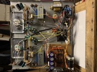
Here are three photos of the most recent attempt to get rid of the hum in the amp.
The white wires going from the raw power supply to the Coleman regulators, and from the regulators to the filaments, are now shielded pairs, with one end of the shield returned to ground with the yellow wires.
I moved the Coleman regulators closer to the sockets, and I added a ground wire to the star ground from each socket mounting plate, which was previously floating with respect to ground.
Previously, I had the raw filament DC supply in a separate steel box. I tried it with and without the box, and it seemed quieter without the box. It is now mounted on a wood platform and not connected to the chassis electrically.
Please let me know if you would like any closeups or other angles for photos.
Attachments
DC Powered filaments:
1. There are lots of rechargeable Lead Acid Gell Cells available, they are 2V.
2. Ignore the following if you are using a well regulated 2.0V DC filament supply for the 30.
AC powered filaments:
How did you implement the hum balance pot and rest of the 2.0VAC filament circuit?
Please post a schematic of the complete filament supply.
It looks like you have parallel series dropping resistors to one side of the filament, but not to the other side of the filament.
You need 1.0VAC from ground to one side of the filament, and 1.0VAC of the opposite phase to the other side of the filament, and the center of those filament voltages need to reference equally to ground.
Since the filament "is" also the "cathode", it takes careful design of the AC filament power circuitry.
How many type 30 tubes do you have to try?
This is important.
I will explain if you wish.
You noticed that the gain with the 6V6 was lower than the gain of the EL84.
And, that the hum was lower with the 6V6 than with the EL84.
That is correct, a constant hum from a type 30, will be quieter when the output tube gain is lower.
6A3:
1. If this most recent attempt to reduce hum doesn’t work, I will try a battery for the 30 filaments next. Even if it does work, I will disconnect the regulators at some point and try battery filaments anyway to see which I prefer.
2. I am using Coleman filament regulators.
I have about thirty 30s. Please do explain.
Yes, the hum is always there, just less audible with the 6V6s. Also, there isn’t enough gain with the 6V6. It sounds nice, but will require the additional gain that my DSP crossover can provide when I use the amp as a treble amp in my two way speaker setup.
When you say the hum was audible between tracks, was the amp running full range speakers or was it amplifying only the upper frequency range which, as I recall, is how you plan to use it?
I was under the impression that you did have the amp breadboarded before transferring parts to a chassis. Perhaps I'm thinking of a different amp in another thread.
FlaCharlie:
For my testing, I am using a pair of La Scala speakers that I usually use to test amps with. The amp in its current form has a reasonably full range OPT, and it is easier for me to judge its sound quality when I test it full range. It does not disappoint. In some respects, it’s my favourite amp so far. It is a bit lacking in the bass, but not any more so than the other triode connected 6V6 or EL84 amps that I have built.
I had a 01A to EL84 amp breadboarded. I was unable to get the hum out of it in its breadboarded form. As I mentioned earlier, breadboarding is pretty useless with my current setup. The (very sensitive) speakers I use are in a different part of the house, and I would have to haul the breadboarded amp there every time I wanted to test it properly. It was an interesting exercise, and I will revisit it, but I need to better setup my work area for it to be an effective tool. Most importantly, I need to find a pair of (or a single) sensitive speakers that I don’t care about to test with.
tizman,
Sorry, I did not read all of the 300+ posts in this thread.
But you are still having hum issues.
Since you are using the Coleman Regulators, they will provide very low ripple DC.
And I missed that you were using those.
If the Coleman Regulators are working properly . . .
The filaments of the 30 are not the issue, no AC or ripple there.
You should be able to properly measure the DC and the very small ripple from the Coleman regulars to make sure they are working properly.
And, that also means you should not need multiple type 30s to try, with good low ripple DC to the filaments.
AC filaments is another story on type 30 tubes, much more difficult to tame hum.
I am sure that the 300+ threads have already advised you to check the B+ ripple that supplies the high voltage to the type 30 plate load.
And, I hope that all forms of ground loops have been properly discussed, and checked out.
Is there any chance that there is a power transformer or filter choke that is spraying AC magnetic fields at the type 30 plate?
If a magnetic part of a tube has an AC magnetic field nearby, it can cause that part to vibrate.
A part of the tube that vibrates will cause modulation of the tube DC current, in this case, it will be at 2X power mains frequency (2 alternations of magnetic field per cycle), and appear as hum.
Is there a complete schematic of your amplifier in the 300+ posts on this thread?
Which Post Number?
We should have been able to solve the hum problem by now, obviously we have not.
Ground loops are perhaps the most tricky cause of hum.
B+ ground loops, input connector and input tube ground loops, negative feedback ground loops, etc.
Wiring layout can also inject into grid circuits.
Wires with lots of ripple current into them can also generate magnetic fields.
The wire from the rectifier to the first cap of a CLC B+ filter, for example.
The wire from the rectifier of the filament supply to the first filter cap for another example.
Then there is the angular orientation of both the power transformer, and filter chokes, versus the angular orientation of the output transformers. There is also the factor of the spacing from power transformer and chokes, to the output transformers.
A magnetic steel chassis can cause hum, especially if the amp is single ended.
It easily couples magnetic hum fields across a 17inch chassis from power transformer and filter choke to the output transformer.
The only tube amp I own that has over 1mV of hum at the output, has a magnetic steel chassis.
Most of my amplifiers have less than 100uV of hum (< 0.1mV).
Should be OK for La Scala speakers, but not for sensitive headphones.
Last edited:
tizman,
I see that you are using the amp for mid and high frequency speaker drivers.
The transient caused by a B+ that has a capacitor input filter has lots of harmonics.
Those harmonics may be at a little lower level, but those upper harmonic frequencies are right where our ears are most sensitive.
I used to call this transient noise "drill motor" noise.
The same goes for filament supply rectifiers that have a capacitor input filter.
"drill motor" noise, not just the smoother 2X, 3X, and 4X power mains frequency.
These transient currents, are the main cause of B+ ground loops, that eventually get into the amplifier signal path.
I use indirectly heated tubes, so my filament supplies are AC.
(I used to use DHTs, but ended up changing them from AC to DC filament supplies).
For my B+, whenever possible I use Choke input filters.
If I do not have enough B+, I will use a small capacitor input filter, 1 to 4uF.
The transient current, and harmonic shape, is less for a 4uF cap than it is for a 40uF cap.
Last edited:
The filament is cathode biased, and the two resistor, the grid leak resistor, and the RCA negative are not tied to the screw. It does look that way in the photo. The entire filament supply floats.
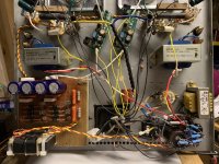
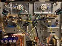
euro21: The above is partially incorrect. The tube is cathode biased, not the filament. Typo! I have attached a few photos of the entire amp bottom as you requested a few posts back.
Is there any chance that there is a power transformer or filter choke that is spraying AC magnetic fields at the type 30 plate?
If a magnetic part of a tube has an AC magnetic field nearby, it can cause that part to vibrate.
A part of the tube that vibrates will cause modulation of the tube DC current, in this case, it will be at 2X power mains frequency (2 alternations of magnetic field per cycle), and appear as hum.
Is there a complete schematic of your amplifier in the 300+ posts on this thread?
Which Post Number?
We should have been able to solve the hum problem by now, obviously we have not.
Ground loops are perhaps the most tricky cause of hum.
B+ ground loops, input connector and input tube ground loops, negative feedback ground loops, etc.
Wiring layout can also inject into grid circuits.
Wires with lots of ripple current into them can also generate magnetic fields.
The wire from the rectifier to the first cap of a CLC B+ filter, for example.
The wire from the rectifier of the filament supply to the first filter cap for another example.
Then there is the angular orientation of both the power transformer, and filter chokes, versus the angular orientation of the output transformers. There is also the factor of the spacing from power transformer and chokes, to the output transformers.
A magnetic steel chassis can cause hum, especially if the amp is single ended.
It easily couples magnetic hum fields across a 17inch chassis from power transformer and filter choke to the output transformer.
The only tube amp I own that has over 1mV of hum at the output, has a magnetic steel chassis.
Most of my amplifiers have less than 100uV of hum (< 0.1mV).
Should be OK for La Scala speakers, but not for sensitive headphones.
6A3:
I tried removing the power transformer and putting it away from the chassis on long leads. This resulted in more hum than when the PT was on the chassis. When I returned the power transformer to the chassis, the hum did not go back down to its previous level. It may be the PT. I will try switching the PT for a different one.
Please have a look at the photo of the amp’s bottom for an idea of the layout of parts. They seem fine to me, and certainly not unlike many of the IDHT amps I have built without any hum.
The chassis is definitely a magnetic steel one. 1 mV at the speakers sounds like what I was getting at the speaker prior to taking off the PT. Now that a I’ve put the PT back on there is a much louder hum.
FlaCharlie pointed out that perhaps I am expecting too much from a 30 DHT, especially on a steel chassis.
Thanks for your suggestions and observations. If I can’t get it to not hum, I’m going to redo it (more carefully) on an aluminum chassis. First I will try using a couple of batteries to power the filaments. Before all that, I’m going to see if my most recent attempt to get rid of the hum worked by testing it on my speakers.
I will post a schematic shortly.

I tested it again, and it still hums. I’m going to try a couple of batteries for the filaments next.
Hi Tiz,
At first, the very long (black) grounding wires from #30 ground points is needless.
At second, the #30 socket screw "grounding" also unnecessary, it's connected to top plate.
The signal (for each tubes separately) loop be so short, as possible.
Create the individual local grounding points for each stage.
The grid leak resistor, the cathode "ground", the stage power decoupling capacitor negative pole (and other part belonging to this stage) must be "grounded" here.
And after it, connect local grounding points to channel ground star point.
The cannels ground star points connected to HV PSU last smoothing capacitor's negative pole.
Finally, the top plate "grounding" must be also so short, mostly near to mains connector (via resistor ... or not ... or floating...)
p.s. Try to separate hum source, disconnect 100nF capacitor leg from EL84 grid. If hum remains, the first stage OK.
Attachments
Last edited:
euro21: I’ll have a look at how what I did is different from your suggestions and change it. The ground point that looks like it’s on the socket screw is actually on the plate that the socket is attached to. That plate is not connected to the top plate because it was set up to reduce vibration, and there is no electrical connection between the socket plates and the rest of the chassis. I added the two ground wires to see they would help, but they made no difference.
My understanding of star grounding is that it is common practice to group the grounds by stage, signal, PS etc. and then run them to the star ground, but that individual wires from each grounding point is the ideal. I will try it both ways to see if it helps.
I just finished rebuilding the power supply, as the measured voltages seemed wrong in some places. The voltage drop between the first and second capacitor should be around 10 volts according to PSUD2, but it measures much less. There may be an issue with one of those two capacitors or the choke. I replaced the choke for a new one of the same model, and swapped out the capacitors as well. I will test again tomorrow.
"That plate is not connected to the top plate because it was set up to reduce vibration, and there is no electrical connection between the socket plates and the rest of the chassis."
In this case why not "grounded" it with 10..100R resistor directly to #30 local star ground point (grid leak and cathode resistor common point)?
Each long black wire is an "antenna", must be leave of its.
p.s. Please read carefully my last sentence in #337 post!
In this case why not "grounded" it with 10..100R resistor directly to #30 local star ground point (grid leak and cathode resistor common point)?
Each long black wire is an "antenna", must be leave of its.
p.s. Please read carefully my last sentence in #337 post!
As you may have surmised, my question about whether you've been listening to it with full range speakers was meant to suggest that the hum may not be audible when the amp is used as you intend - with an active crossover for the higher frequencies only.If I can’t get it to not hum, I’m going to redo it (more carefully) on an aluminum chassis. First I will try using a couple of batteries to power the filaments. Before all that, I’m going to see if my most recent attempt to get rid of the hum worked by testing it on my speakers.
While it would be ideal to eliminate the hum, if it turns out that it's inaudible when the amp is used with the crossover, you might just want to call it "good enough" and forgo the effort of rebuilding it using an aluminum plate or with separate PS chassis.
I understand that harmonics might still be present and measurable. I don't have the ability to measure such things so my criteria for what's "good enough" is based solely on what I can hear. YMMV, of course, so do whatever is necessary to make you comfortable with the result.
- Home
- Amplifiers
- Tubes / Valves
- DHT driver for triode wired SE EL84, 6V6 or EL34