Tizman....one quick check, you can put any 9pin or 8pin idht driver and see what happens,
pinning down source is important.
Regards
I’ll start by moving the PT off the chassis first. Rewiring for a different tube is more difficult. If the PT solves the problem, I’ll probably switch the amp to a different circuit or scrap it and start over on 2 chassis, one for circuit and the other for power supply.
Some DHT ridiculously sensitive to radiated noise -mostly mains hum-.
Some years ago I measured a few bunch of #26 tubes.
The worst ones "produces" even 40dB greater 50Hz FFT component than best ones.
If the steel plate magnetizes, anything can happen.
I can’t think of anything else that could be the problem. I believe that an aluminum top plate instead of a steel one would help. Having the power supply in a different chassis is probably best though. I can say that it is worth the trouble, as the amp sounds great even with the hum.
It's really incredible.
It's like as inductive ringing goes down.
Are you sure, that top plate does not transmit magnetic flux from power transformer?
Steel plates notorious sources of elusive things.
If you can, try to extend PT wires and temporarily put PT beside the amplifier.
I just finished removing the power transformer from the chassis. I put it on long leads that let me place it about three feet away from the amp. The hum is even worse this way. There is a lot more wire now, although most of it is away from the top plate.
Now, when I turn off the amp, the hum disappears immediately. I'm not sure what this means. Is the hum from the power transformer or is it being picked up by the wiring in the circuit?
The only other magnetics in the amp are the filament transformer and a choke in the power supply. I tried moving the filament raw DC supply away from the chassis already, and that did not help. I have also already tried removing the choke and replacing it with a resistor, and that also didn't reduce the hum.
Perhaps the hum is being picked up by the DHTs directly? I tried putting shields on them already, and it made no difference.
I'm not sure what to try next. I'm at the point where it seems best to scrap the amp and try again in two chassis.
If the turn off phenomenon gone, it's probably was an induction.
Next tries:
1.) Try to "ground" upper plate to mains safety ground via 10R, through switch (grounded/floating).
2.) Try building "monoblock" amp.
Each channel must have their own "grounding ridge", where all component (input RCAs too!) of channel grounded.
The two channel grounding tied together only on HV supply last capacitor negative pole.
3.) It's not so difficult (now 🙂 ) to build a temporary HV supply besides the amp:
PT, rectifier tube, capacitors, choke.
4.) Try separated filament supply transformer for DC heating (insulates from plate), and another for power tubes.
A quick update. If I turn off the amp and remove the rectifier tube, and then turn it back on, the hum is still there without the rectifier tube, and it fades away gradually, probably as the capacitors drain. There is no hum at all with the 30 tubes pulled.
If the turn off phenomenon gone, it's probably was an induction.
Next tries:
1.) Try to "ground" upper plate to ,mains safety ground via 10R through switch (grounded/floating).
2.) Try building "monoblock" amp.
Each channel must have their own "grounding ridge", where all component (input RCAs too!) of channel grounded.
The two channel grounding tied together only on HV supply last capacitor negative pole.
3.) It's not so difficult (now 🙂 ) to build a temporary HV supply besides the amp:
PT, rectifier tube, capacitors, choke.
4.) Try separated filament supply transformer for DC heating (insulates from plate), and another for power tubes.
Thanks for your help with this!
The hum is worse now that I have moved the power transformer off the top plate. If it was induction, why would it still hum with the power transformer away from the amp?
1.) I will try to ground the top plate through the mains safety ground via a 10R resistor and through a switch so that I can try it grounded and floating. In order to do so, I will have to remove the power inlet, which is metal and isf electrically connected to the chassis. Thanks for pointing this out, as the inlet being attached to the chassis may be messing up my grounding.
2.) I may try this next, but I think that using separate chassis for the circuit and for the power supply might also be a good plan.
"The two channel grounding tied together only on HV supply last capacitor negative pole." I currently have a separate lead to star ground for every capacitor in the power supply. Is this okay?
3.) As there may be an issue with the existing power supply, and I already have the power transformer outside the amp, I can try to do what you suggest to see if it helps.
4.) I already am doing this, as I have the power tubes on the 6.3 Volt winding on the main power transformer, and I am using a separate transformer and raw DC supply, along with Coleman regulators, for the 30 tubes.
I will try again tomorrow.
Thanks again for the help and suggestions. I have a feeling that the power inlet grounding could be causing the problem.
Is the power inlet the filtered type ?
These can cause a number of problems with DC supplies.
- there is usually a "Y" Capacitor (Line to safety earth), which can couple mains line noise to the chassis.
These caps help appliances with mains→DC converters get through statutory EMC testing, but they are unhelpful in other schemes. You can sometimes remove or disconnect the cap.
The filtering inductance is also unhelpful, and gets excited by the pulse-current behaviour of DC supplies.
A plain inlet is best.
One other check. How wide is the loop area of the 30's grid circuit?
If the 30 is the first tube in the amp, the grid signal enters at the input socket, goes though some wiring to the valve base, then the return side runs from the filament (+ side) to the 0V (B+ return) point, and then back to the input socket.
That may be a simplification, but the circuit traces out as a loop-area. Ideally, it should be a long thin area between grid signal and ground. But if the grid wiring is laid out with ground a long way from it, the loop area increases.
Running a twinax cable (2-core shielded, like microphone cable) between input socket and valve-base is sometimes a useful fix, and may be appropriate where there is a steel chassis. Big loop area for the grid makes the circuit very susceptible to any fields that are floating around - it's the electromagnetic "moment".
If the 30 has cathode bias or filament bias, the 0V of the input socket wires to the 0V side of the cathode resistor, instead of the valve-base. This point should not be located too far away from the valve-base, to keep the grid loop-area as small as possible.
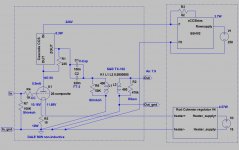
If it helps, attached my #26 preamp schematic and input->tube part picture.
The input selector switching both "cold" and "hot" wire of RCAs.
From input selector the signal "cold" and "hot" wires go to the #26 tube grid leak (Shinkoh) resistor.
From grid leak resistor "cold" point black wire goes to the channel ground bus.
The R.C regulator is near to the tube (on the side of heatsink) -next to input selector switch-.
The 10R 50W filament bias resistor "cold" point goes to the ground bus.
The power supplies are in the PSU box, connected to preamp box via umbilical.
The channels "ground" tied together only in PSU box.
Attachments
Last edited:
Is the power inlet the filtered type ?
These can cause a number of problems with DC supplies.
- there is usually a "Y" Capacitor (Line to safety earth), which can couple mains line noise to the chassis.
These caps help appliances with mains→DC converters get through statutory EMC testing, but they are unhelpful in other schemes. You can sometimes remove or disconnect the cap.
The filtering inductance is also unhelpful, and gets excited by the pulse-current behaviour of DC supplies.
A plain inlet is best.
Rod: I switched to a plain inlet without any filtering, but the problem persists.
One other check. How wide is the loop area of the 30's grid circuit?
If the 30 is the first tube in the amp, the grid signal enters at the input socket, goes though some wiring to the valve base, then the return side runs from the filament (+ side) to the 0V (B+ return) point, and then back to the input socket.
That may be a simplification, but the circuit traces out as a loop-area. Ideally, it should be a long thin area between grid signal and ground. But if the grid wiring is laid out with ground a long way from it, the loop area increases.
Running a twinax cable (2-core shielded, like microphone cable) between input socket and valve-base is sometimes a useful fix, and may be appropriate where there is a steel chassis. Big loop area for the grid makes the circuit very susceptible to any fields that are floating around - it's the electromagnetic "moment".
If the 30 has cathode bias or filament bias, the 0V of the input socket wires to the 0V side of the cathode resistor, instead of the valve-base. This point should not be located too far away from the valve-base, to keep the grid loop-area as small as possible.
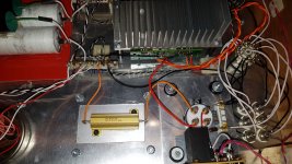
Please have a look at the attached photo for details on the inlet to valve construction. The RCA inlet is in the top right of the photo, and the 30 socket on the left.
The white wire is shielded and goes to the grid. I had the white wire's shield connected to ground prior, but in this photo it is disconnected. The hum is the same either way.
All black wires go to a star ground. The twin blue resistors are the cathode resistors for the 30. Cream coloured resistor is the grid leak. Purple wires come from the filament regulators. The green wire brings B+ to the plate. The metal portions of the valve base are attached to a rectangular metal plate that is not electrically connected to the top plate.
I have tried grounding and floating the ground of the speaker jack with no change to the hum.
Holding the loose transformer and moving it around the top plate generates extra hum only when the transformer is very close to the 30 tubes.
Before removing the power transformer, the amp had a quiet, but still audible, hum. It did sound great though. With the PT removed, and longer wires attached to the PT in order to position it away from the chassis, the hum is very loud. Taking the PT off the chassis made the hum much worse. It was not what I expected.
My feeling at the moment is that I have made an error in the wiring of the amp somewhere that is causing this problem, or that in my attempts to repair the amp I have loosened or broken a connection or solder point. Tonight I will go through the amp point to point checking part values and solders.
Please let me know if there is a problem with the wiring. It was all much neater before, but I have switched so many things around that it isn't anymore...
Attachments

Last edited:
If it helps, attached my #26 preamp schematic and input->tube part picture.
The input selector switching both "cold" and "hot" wire of RCAs.
From input selector the signal "cold" and "hot" wires go to the #26 tube grid leak (Shinkoh) resistor.
From grid leak resistor "cold" point black wire goes to the channel ground bus.
The R.C regulator is near to the tube (on the side of heatsink) -next to input selector switch-.
The 10R 50W filament bias resistor "cold" point goes to the ground bus.
The power supplies are in the PSU box, connected to preamp box via umbilical.
The channels "ground" tied together only in PSU box.
euro21: Thanks for the schematic. The schematic is for filament bias, so you have the negative filament connected to the ground of the input jack and to ground generally.
In my photo, the only connection to ground that the filaments have is through the 30's cathode resistor. Is this the right way to do it?
You show both a grid leak resistor and a 1K grid stop resistor. I didn't include a grid stop resistor. Should I add one?
The grid wiring looks good - I don't see any risks with that.
Is the filament trafo still a Hammond 229B16 ? This should work very well: it's designed for low external flux, and the split-bobbin design means low coupling of common-mode noise from the primary.
If moving the PT away from the chassis increases the hum, this suggests it is a victim, rather than a villain. Filament supply trafo (and Raw DC parts) are susceptible to common-mode noise, simply because you can't ground them. So the chassis may have been shielding the 229B16 from the HV PT, or the rectifier.
Using shielded (twinax, audio 'patch' cable, or microphone cable) cable from the Raw DC board to the regulator input is worth trying, if you have some cable at hand.
The wiring between HV PT and rectifier, and from rectifier to HV caps also needs to be short, and neat, or it can also cause coupling to the filament supply.
Please let me know if there is a problem with the wiring.
Hi Tizman,
Is the filament bias resistor-grid leak resistor-RCA negative tied to #30 socket M3 screw?
The whole ground wire/bus structure must be insulated from top plate. Please measure it.
It would be nice to see the whole bottom wiring.
71a as driver with EL84 SE is good 1.5W amp.
Sample: a little modified RH84
That OT : How can I simulate that in LTspice? Need to know the Lprim and Lsec. Do simply take k=1 for simulations?
Sorry for responding so late.
Hi Joe,
It has measured parameters of simple 5k:8 transformer.
The origin made by Stephie (Steve) Bench:
:: View topic - Drop down transformer models for LTSpice
Rename xfrassy.txt to xfrm.asy.
Put the xfrm.asy to the LTSpice .../sym/"ownlibrary" folder, and XFRM.txt near the *.asc file.
If you can measure this parameters of your OPT, you can generate own model.
Attachments
The grid wiring looks good - I don't see any risks with that.
Is the filament trafo still a Hammond 229B16 ? This should work very well: it's designed for low external flux, and the split-bobbin design means low coupling of common-mode noise from the primary.
If moving the PT away from the chassis increases the hum, this suggests it is a victim, rather than a villain. Filament supply trafo (and Raw DC parts) are susceptible to common-mode noise, simply because you can't ground them. So the chassis may have been shielding the 229B16 from the HV PT, or the rectifier.
Using shielded (twinax, audio 'patch' cable, or microphone cable) cable from the Raw DC board to the regulator input is worth trying, if you have some cable at hand.
The wiring between HV PT and rectifier, and from rectifier to HV caps also needs to be short, and neat, or it can also cause coupling to the filament supply.
Rod: Yes I’m using the Hammond 229B16. In previous trouble shooting, I detached the filament PT and raw supply from the chassis plate, as it was in its own little steel box. Moving this steel box away from the chassis had no effect on the hum.
The hum increased when I took the HV power transformer off the chassis, but I don’t think it was because I moved it away from the chassis. Holding the transformer and moving it around the chassis only increased the hum when I put it right next to the 30 tubes. I think I broke or moved something in the process of removing the HV PT off the chassis.
I have a quantity of shielded cable, and I will try using it to get DC from the raw supply to the filament circuit, and then to the filaments.
The power supply wiring is relatively short and neat. I think I have made an error somewhere and haven’t found it yet.
Hi Tizman,
Is the filament bias resistor-grid leak resistor-RCA negative tied to #30 socket M3 screw?
The whole ground wire/bus structure must be insulated from top plate. Please measure it.
It would be nice to see the whole bottom wiring.
The filament is cathode biased, and the two resistor, the grid leak resistor, and the RCA negative are not tied to the screw. It does look that way in the photo. The entire filament supply floats.
Part of me is wondering if you're just expecting too much from the 30 in terms of hum.Before removing the power transformer, the amp had a quiet, but still audible, hum. It did sound great though.
When you say the hum was quiet but still audible, if that was at idle with no music playing, it might be as good as can be expected from a 30. After all, the 30 does have a reputation for having more hum than some of the other DHTs.
Obviously, if it was audible with music playing, that's not acceptable.
Also, it might be helpful if you could post a pic of the entire under-chassis area. There may be something about the overall layout that's influencing the hum.
Just to rule out any issues with the filament supply, I would suggest you temporarily try to heat the tube with a battery which is, of course, what it was designed to use.The filament is cathode biased, and the two resistor, the grid leak resistor, and the RCA negative are not tied to the screw. It does look that way in the photo. The entire filament supply floats.
The filament is 2v and only .06a. A single AA battery will give you 1.5v and starving the filaments tends to help too.
- Home
- Amplifiers
- Tubes / Valves
- DHT driver for triode wired SE EL84, 6V6 or EL34