Thanks jhstewart9 and, yes, I hear you Chris. I listened to the circuit in post #336 last night without elevating the heater voltage (it was before jhstewart9 replied) and it was fine.
6SN7 in SRPP is certainly better than the series voltage amp arrangement I tried earlier. To my surprise, this circuit has more than enough gain to drive the speakers to a loud volume from a 2V source (my laptop, volume on full, streaming Tidal, connected to amp input via headphone-->RCA cable). I've got the volume pot at about 1/2 at the moment, and it becomes excessively loud the further right I turn it. I'd thought for sure this would need a preamp because of the calculated 3V input sensitivity.
Anyway, this circuit is very good. It doesn't have quite as much liveliness as 6SL7 SRPP, nor as much inner clarity. I thought part of the sonic signature might have been due to the carbon film resistors or the Sylvania 6SN7s. So, this morning I swapped in a nicer pair of Raytheons from my main system and there is an audible improvement. I suspect it might improve audibly again if I were to change these CF 1K resistors for wirewound ones.
I'll listen for a few more hours and then will try the wirewound 2.2K resistors I have on hand, which will bring the 6SN7 sections to a 150Vak/2.5mA operating point (just north of the calculated minimum signal current to avoid slewing). That's a bit low in the plate curves if you have a TBMF in the datasheets, but then so is the same parameter in my favorite arrangement so far, 6SL7 SRPP.
Update: there is a little bit of graininess in complex program material like Ravel's "Bolero" that I don't recall from the 6SL7. Timbre of acoustic instruments, as well as attack/decay, is good but not great.
Last edited:

Some Wirewound resistors have moderate inductive reactance (a possible concern at high audio frequencies).
Depending on where in the circuit they are, they can either reduce the amplitude of high frequencies, or they can increase the amplitude of high frequencies.
That sounds like a potential change in the sound character of a circuit.
In general, the effect is (however small or large):
In the Plate circuit, there is increased amplitude of high frequencies
In a cathode follower, there is increased amplitude of high frequencies
In a common cathode circuit without a bypass capacitor, there is reduced amplitude of high frequencies
There are other circuits that may be similarly affected.
Often times, there is no noticeable effect.
Sleep well at night.
Your Mileage May Vary
Last edited:
Watch out for Limiting values of Rkf (loop resistance, heater to cathode).Decouple from the cathode with something like 100K & bypass that to common with 0,1 micrioF.
That way if there is a problem in the heater line it does not remove the bias from the power audio tube.
It's 20k for ECC82 in many applications - This from Philips, for example (1959 DS):
THX for posting that Rod, altho it must have been on some of the data sheets I have I've never noticed it before.
I built a pair of PP UL 6L6GC Amps circa 1960 for my own use. And they completely ignore this requirement but
ran everyday for 17 yrs without incident. Then onto the shelf, a real job had brought money to buy Sansui.
More recently the coupling caps have been replaced, they both still run OK but are sitting here in
the workshop on the shelf.
Perhaps the problem was solved when quite a few tube types had to be modified to work in equipment
whose heaters ran directly off the power line, without an isolating transformer. Just guessing tho.
Attachments
An interesting thread, as I'm currently collecting parts for an 6S4S (6B4G) SET, close enough to 2A3 I guess. Has anyone tried CV1135 (~6J5 with top caps) - LL1660/10mA - 2A3?
I have a pair of LL1660 and some CV1135 on the shelves and this combination might be the first thing to try when I get the prototype up an running.
Probably with the 1660 wired as 4,5:4 to get a small stepdown, as I believe it may sound better than 4:4,5.
I have a pair of LL1660 and some CV1135 on the shelves and this combination might be the first thing to try when I get the prototype up an running.
Probably with the 1660 wired as 4,5:4 to get a small stepdown, as I believe it may sound better than 4:4,5.
Very busy over the last few days though I did manage to swap in 2.2K resistors to the 6SN7 SRPP input circuit, which ran each half at 150Vak/2.4mA. The sound is rich, and a little more lively than when the 1K resistors were in place and it ran at 150Vak/4.5mA per half. Both 6SN7 SRPP variants I tried tended to get bogged down a little in complex music passages. To sound its best, I think it would need to be run at higher voltages for more power, and for that reason might need to precede the output tube in the power supply series. Anyway, I like this latest version, but still prefer the 6SL7 SRPP, which I've put back on the breadboard for comparison.
6SN7 cathode follower in my main system sounds much better to me than 6SN7 in SRPP, probably because the halves are running at more optimal op points. There's no need to bother with CF here
If I go with a cap-coupled design for a final build, it will be 6SL7 SRPP with the 2.2K resistors.
Once work is done for the week I'll move on to the next stage of the process: direct-coupled circuits with 6SF5 on input, starting with the old Lipman circuit (Fi 2A3) posted way back at the beginning of this thread, then on to the "updated" Fi 2A3 (also shared earlier), and then on to my own tweaks, whatever those might be. Tbh, they don't look very good on paper so I'll be curious to hear why people make similes with "honey" and "nectar" and swear it's the bees knees.
Take a 6SF5 Octal dual triode.
Reduce the size of the elements, spacings, etc. in a way that will give the same characteristics (u, Gm, rp, etc.)
Put that into a 9 pin Noval glass envelope.
What do you get . . .
It is called a 12AX7 (The biggest difference other than size, is the different mechanical resonance frequencies and resonanc Qs).
Understood, but I've always been disappointed with the sound of noval tubes in power amps. Always.
I guess you can say that the Octal tube resonances are less offensive to you than the Noval tube resonances.
Have you ever heard of varying Electrostatic forces activating those mechanical resonances?
Most have not.
An electrostatic field attraction exerts a force from one tube element to another tube element. If the voltage varies (such as it does with large signal swings), the electrostatic attraction changes as the signal voltage changes.
Now, make the signal frequency = the mechanical resonance frequency.
You can guess what happens.
A similar effect is when a large marching group marches across a bridge. It does not happen at once, it takes time for the resonance to build up significant energy.
Just saying
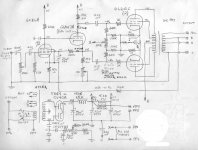
Just posting the schematic for final build candidate #1. Values shown reflect what is on the breadboard right now.
This is the best sounding cap-coupled circuit to my ears so far. Note that I lowered the input stage power supply resistors from 27K to 6.8K, which runs the 6SL7 halves closer to 150V/0.7mA each, which sounds better than the ca. 140V they were at before.
Edit: the PS filter cap connected to the 6SL7 upper triode plate is 47uF/450V.
Kind of a lot of work to arrive back at the well known JE Labs 2A3 / 6SL7 SRPP (with a couple of tweaks), but I’ve learned a lot in the process.
After I’m done listening today, I’ll break down the breadboard and set it up for the direct-coupled circuits I intend to try.
Attachments
Whenever you use RC coupling to a 2A3, measure the 2A3 grid voltage to ground.
(0.0V at the 2A3 grid).
Any appreciable voltage at that grid indicates one of the following:
Leaky coupling cap (replace it; sometimes with a different kind of cap).
The 2A3 g1 grid resistor is too high (lower the resistance).
A leaky 2A3 tube (replace it).
dissipating more than 15 Watts in the plate.
Any of those can affect the sound of the amplifier.
The SRPP should be able to drive far less Ohms than a 470k g1 grid resistor.
Just my opinions
Last edited:
2A3 running <300V supply with 750R cathode bias & 470K grid resister = All AOK.
No reason to sweat, the cathode bias will follow the grid a long way.
At DC the tube looks like a CF, most of its load is in Rk. Rest in the OPT primary DCR
Any problems will by then be very apparent.😀
No reason to sweat, the cathode bias will follow the grid a long way.
At DC the tube looks like a CF, most of its load is in Rk. Rest in the OPT primary DCR
Any problems will by then be very apparent.😀
Can I ask you what speakers (or headphones?) have you used to get these conclusions?I've spent years and years working on 300b and 2a3 circuits. My findings were these:
- 2 stages always sounded better than 3 stages
- DHTs sounded better than IDHTs
- 2 stages with all-DHTs needed more gain
Speakers are Wharfedale Program 30D-6. Quite ordinary 2-ways but with a good sound and very easy to listen to for prolonged periods. Mid-bass is polypropylene and similar to the B110 used in LS3/5A, bit smaller magnet. 3/4" tweeter.
Your using a 0,082uf cap with a 470k resistor? That is just one break point in the ssytem.Just posting the schematic for final build candidate #1. Values shown reflect what is on the breadboard right now.
This is the best sounding cap-coupled circuit to my ears so far. Note that I lowered the input stage power supply resistors from 27K to 6.8K, which runs the 6SL7 halves closer to 150V/0.7mA each, which sounds better than the ca. 140V they were at before.
Edit: the PS filter cap connected to the 6SL7 upper triode plate is 47uF/450V.
Kind of a lot of work to arrive back at the well known JE Labs 2A3 / 6SL7 SRPP (with a couple of tweaks), but I’ve learned a lot in the process.
After I’m done listening today, I’ll break down the breadboard and set it up for the direct-coupled circuits I intend to try.
You are losing a whopping ~17% of the bass at 20hz. 8.5% at 40hz, 4.2% at 80hz, and 2% at 160hz.
I was wondering if you are planning on using a separate sub woofer?
cheers
pos
-3dB at 4 Hz (which is what 470k / 0.082 uF gives) seems OK to me, especially for a single ended amp where the transformer might struggle at very low frequencies.
"-3dB at 4 Hz (which is what 470k / 0.082 uF gives) seems OK to me, especially for a single ended amp where the transformer might struggle at very low frequencies."
One would easily have weak bass which would influence even voices. With 1st order, 6db/octave,
-3db at 4hz would be ~1.25db, at 8hz ~-.6db, at 16hz ~-.2db, at 32hz -0.7db, at 64hz, -0, 3db,
at 128hz, and even 0,12db or so at 256hz. Is it quite perceivable in an excellent system.
Even according to RANE corp, a small deviation of more than 1/3 octave and will be perceived.
However, due to electrolytic capacitors and other poor quality parts in the designs customarily used,
the masking may be enough to cover one "situation".
I have been dealing, R&D, with 1 part per million in crossover resistance values, which covers many octaves
bandwidth and is easily perceived. In fact, in lab tests, I have been down to 1 part in 3,000,000 before
concluding no sonic difference.
Besides that, there are many other break points, including the OPT, that add -dbs.
For instance, if we had just two breakpoints, each at 4hz and -3db, we would be -6db down at 4hz.
If we had one break point of -3db at 4hz and a -1db at 4hz, we have -5db at 4hz.
The point is there are many breakpoints in a system and they all degrade the music.
One must "over kill" to have proper response.
cheers
pos
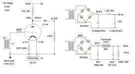
Yes, it's perfectly possible to build a PSE 2a3 amplifier. And a 10Y would be a perfect driver. That would be a very nice amp. I don't have a schematic, though. The 1140-LN-C on the front end would be fine. The only thing you would have to consider carefully is the OPT. I imagine that 2.5K and at least 120mA would be in the ballpark. No idea of who makes such an OPT, though Hammond 1627SEA is one possibility that fits, 2.5K and 160mA.
https://www.hammfg.com/electronics/transformers/audio/1627-1642?referer=968
In fact I have a perfect mains transformer for this, which came from a PSE 2a3 amp. I'm not using it so I could sell it. I'm in London.
https://www.hammfg.com/electronics/transformers/audio/1627-1642?referer=968
In fact I have a perfect mains transformer for this, which came from a PSE 2a3 amp. I'm not using it so I could sell it. I'm in London.
Thank you for the quick reply. I have one more question from the "newbie wants to learn something" series, namely Rob's regulator. In the schematic I see that it is only used for the 10y tube, would it be a good idea to use it also for the 2a3 tube? And if so, in the case of the PSE 2a3 amplifier with a 10y driver, would it be a good option to connect Rob's regulator to each of the 3 tubes in the monoblock separately? So that the adjustment of each of the 6 tubes in the stereo amplifier can be carried out independently of each other?
I would probably commission someone to build the output transformer, but I would need to know the parameters. I understand that a 2500 40w would be a suitable transformer.
As for the power transformer, I will definitely contact you when I know all the details of the project and when I decide to build it.
So far I've managed to build several , very simple tube amplifier, The last one is a direct coupled 2a3 to 6sl7. So I already know how to "read" schematics, I know how to be safe during construction, only a little knowledge is missing 😉 I love the sound from my amplifier, I just need a little more power, hence the idea of PSE 2a3 and I would like to try full dht. I reject amplifiers on other tubes such as 300b, kt88 etc. just as for m ie sound 2a3 is without competition. Well, I haven't heard of 45 yet. But that's out of the question because of it's low power.
- Home
- Amplifiers
- Tubes / Valves
- Developing a 2A3 SET