@hires,
It should be in balanced if you don't see any red LEDs.
Or, just measure the voltage over the two ultra capacitors.
Ian
It should be in balanced if you don't see any red LEDs.
Or, just measure the voltage over the two ultra capacitors.
Ian
Ian,
On the UcHybrid board there are only two LEDs:
D2 Power indicator and D1 condition indicator.
There is no overvoltage indicator.
In this situation it's impossible to understand that there is an ongoing imbalance.
Regards
On the UcHybrid board there are only two LEDs:
D2 Power indicator and D1 condition indicator.
There is no overvoltage indicator.
In this situation it's impossible to understand that there is an ongoing imbalance.
Regards
When UcHybrid is fully charged, the voltage on each ultra capacitor will be only 1.65V, that's far from the 2.7V rated voltage. So, UcHybrid was designed to use passive balancer. There will be enough headroom and time to reach the balance point if the voltages are slightly different over the two UCs.
Ian
Ian
Hello,
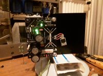
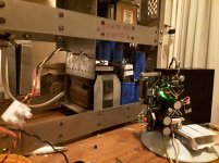
Today i kind of finished a LCRC supply followed by a regulator circuit designed by Doede Douma to feed my lifepo4 board from Ian.
I will use the 5 volt 2A supply followed by a Ucconditioner board for the Raspberry.
AND 4 lifepo4 cells from which 3 will be followed by UcHybrid board for some small consumers.
The 5 Volt will be eating all the time and the 4 lifepo4 will just consume a lot when charging.. Once charged they will recharge at different intervals i guess because not all circuits will take the same current.
The supply now can supply around 2A continuously at 15 volt and then have enough voltage drop across regulator circuit to achieve very low ripple.
If i connect a kind of load resistor across each of the 5 supplies will i be able to check if the supply will be powerfull enough to charge everything? When there will be more than 2 A the voltage drop can become to low so ripple will go up but that will be temporarily.
Any ideas welcome, Eduard
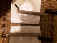
P.s As you can see i had to use some big resistors taken from a welding machine to create a proper load
Today i kind of finished a LCRC supply followed by a regulator circuit designed by Doede Douma to feed my lifepo4 board from Ian.
I will use the 5 volt 2A supply followed by a Ucconditioner board for the Raspberry.
AND 4 lifepo4 cells from which 3 will be followed by UcHybrid board for some small consumers.
The 5 Volt will be eating all the time and the 4 lifepo4 will just consume a lot when charging.. Once charged they will recharge at different intervals i guess because not all circuits will take the same current.
The supply now can supply around 2A continuously at 15 volt and then have enough voltage drop across regulator circuit to achieve very low ripple.
If i connect a kind of load resistor across each of the 5 supplies will i be able to check if the supply will be powerfull enough to charge everything? When there will be more than 2 A the voltage drop can become to low so ripple will go up but that will be temporarily.
Any ideas welcome, Eduard
P.s As you can see i had to use some big resistors taken from a welding machine to create a proper load
Attachments
This thread has inspired me to build a battery preamp, but I am stuck on something and I am hoping someone can give me some advice/pointers.
I would like to build a system that has two battery banks per channel. While one bank is in use, the other bank is being charged. When the active bank drops below a certain voltage, the whole circuit shuts off, the active bank is deactivated and put on the charging circuit, and the fully charged circuit is taken off the charger and put into active use. Once the hand off happens, the preamp turns back on again.
My first question is whether or not this is even a good idea.
My second question is - is there a ready made BMS that can do something like this, or do i have to make one.
Thirdly - If I have to make one, what is the most elegant way to accomplish this task?
Thanks in advance for any guidance.
Hello,
Will just connect everything today and see what happens!
The big lifepo4 board will be old school soon because the new kid on the block is just using BIG supercaps.
Ian is hunting deer in a remote area but customers can always share ideas as you can see.
There is almost no useful info in the '' clock related threads '' anymore.
I will start my own Sinepi thread once i got it.
Of course will let you know if the lifepo4 is working.
Greetings, eduard
Hello to all:
I am a reader of this interesting discussion and I would like to inform those who still do not know them about the new SAB Mosfets made to control and balance supercapacitors in a precise way and without consuming energy. It seems to me that these devices are not mentioned here so far.
Next I would like to ask a few questions about supercapacitors.
I state that I have no interest with the following manufacturer or commercial interests of third parties, but I find the product very interesting.
ADVANCED LINEAR DEVICES, INC. has marketed the following Mosfets:
ALD8100XX / ALD9100XX SUPER CAPACITOR FAMILY
AUTOMATIC BALANCING MOSFET ARRAY (SAB ™)
These SAB Mosfets are available in chips for two or four supercapacitors in series and other chips can be added in series. The device must be chosen on the maximum voltage to be reached on each supercapacitor during charging. The extraordinary thing is that the balancing and control work they do is practically without current dissipation.
The voltage ranges provided by the manufacturer start from 1.6V, 1.7V up to 3V. What interests me is the 1.7V voltage to obtain with 4 supercapacitors 3000F the voltages I need 3.4V, 5.1V, 6.8V to power: Oscillator, RPI-Reclocker and DAC, if the deviation from the nominal values is not too high ( 3.3V and 5V, 6.7V), otherwise I could choose the value of 1.6, getting 3.2V, 4.8V and 6.4V.
To do this it is necessary to use a power supply suitable for charging supercapacitors, which disconnects with a relay as soon as the desired voltage is reached.
The various DAC devices etc. powered by supercapacitors would be connected directly to them and with cables as short as possible.
These SAB mosfets are found on the market by large distributors but unfortunately for now at prices too high for the minimum quantities required, 50 pieces, the unit price seems acceptable to me around 3.5 dollars for 50 pieces.
In addition, a PCB is also sold with the SAB Mosfets already mounted for two or four capacitors "SABMB16 / SABMB810025 / SABMB910025 / SABMB8100XX / SABMB9100XX"
My Dac is powered at 6.8V and has LDO regulators that bring the voltage to 5V x 2 and 3.3V, the double 5V powers the Digital and Analog circuits of the DAC separately, with currently two separate power supplies up to the transformer. Then I have two more 5V power supplies that I use for the Recloker and the RPI.
Since 5V is the same value that RPI and Reclocker use, given the very low internal resistance of the 3000F supercapacitors (which is almost a short circuit), paralleling all 5V supplies bypassing the LDOs on the DAC (using only 3 supercapacitors instead of four) and powering the oscillator at 3, 4V separately, do you think I would have a deterioration in audio performance, or would the very low impedance of the supercapacitors eliminate any interference between the various devices?
I would like to read the opinions of those interested in the subject.
Thanks.
John
This thread has inspired me to build a battery preamp, but I am stuck on something and I am hoping someone can give me some advice/pointers.
I would like to build a system that has two battery banks per channel. While one bank is in use, the other bank is being charged. When the active bank drops below a certain voltage, the whole circuit shuts off, the active bank is deactivated and put on the charging circuit, and the fully charged circuit is taken off the charger and put into active use. Once the hand off happens, the preamp turns back on again.
My first question is whether or not this is even a good idea.
My second question is - is there a ready made BMS that can do something like this, or do i have to make one.
Thirdly - If I have to make one, what is the most elegant way to accomplish this task?
Thanks in advance for any guidance.
I have built modules that alternate between 2 LifePo4 batteries for constant, clean 3.3V using Arduino code & controller, relays, TP5000's to charge, and a couple of perf board stacked with standoffs.
Some of them also incorporate supercapacitors, managed with power resistors and additional relays to avoid current rush issues.
Ian's solution is more sophisticated - I just wanted to do it myself and to also have 24/7 power for clocks and such without needing to worry about doing anything to trigger a recharge.
If using an IoT music player like Volumio, it is possible to incorporate an ESP8266 or ESP32 to ensure no relays clicking while music is playing.


if the charger is charging in series ( 13.2 v ) and the Arduino and relays etc. are running off 1 cell (3.3v), does this not cause a charging / discharging imbalance?
Hi Ian,
Could I connect two UcPure in series to get higher voltage?
Thanks!
Yes, you can.
Ian
My MKIII project hasn't gotten off the ground yet so I opened a classifieds listing if anyone is interested in spare parts:
https://www.diyaudio.com/forums/swa...po4-supercap-addons-maxwell-scs-new-post.html
I'm not sure which direction I'm pursuing, but if I offload some parts it will make decisions more flexible. I'm definitely keeping the MKIII in the mix.
https://www.diyaudio.com/forums/swa...po4-supercap-addons-maxwell-scs-new-post.html
I'm not sure which direction I'm pursuing, but if I offload some parts it will make decisions more flexible. I'm definitely keeping the MKIII in the mix.
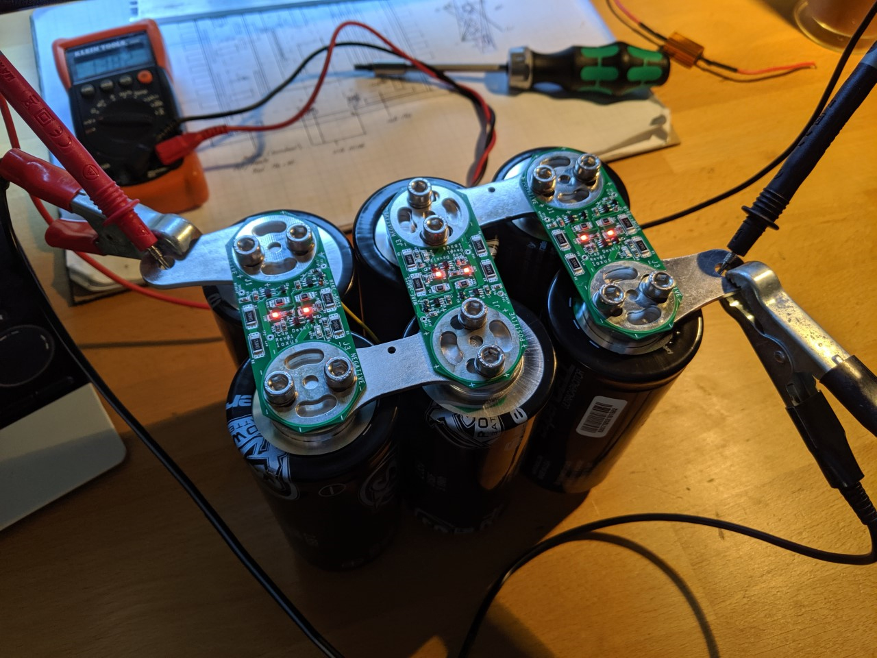
Now it turns even more crazy.
This is a UcPure in 15V configuration with 6*3000F ultracapacitors.
When powered on, only the fully charged ultracapacitor pack will be applied to the load. It will be a pure UC power supply and 100% isolated from any rest of the circuit.
No doubt this is the best 15V power supply in the real world. And it will be the best power supply for Andrea’s TWTMC clocks.
Why?
Actually ultra capacitor has two different working modes.
UcPure works in the first mode which I call it the class A mode. In this mode, only ultracapacitors apply to the load. No other active power supply is involved. The current goes only one direction out of the ultracapacitors into the load. Class A mode will ensure the best low ESR and low noise performance.
Another mode I call it the class B mode. In this mode, ultracapacitors work as class B shunt elements in parallel with another power supply or charger. The current goes both directions into and out of the ultracapacitor. Though the performance of this mode is still better than other active power supplies, but the dynamic ESR will still be higher than the class A mode because the ultracapacitor current crosses zero frequently. And even more, the noise of the power supply that attached can still be introduced into the voltage rail to make noise performance worse than the class A mode.
The sound quality difference between class A and class B can be heard clearly if we use them as power supplies for clock circuits such as the FifoPi clean side or the TWTMC oscillators.
UcPure is a heavy duty design for a durable operation. It can use both AC and DC as input. The quality of the input doesn't matter because the input will be disabled when UcPure is turned on.
Ian
This is great. And I am entirely willing to go along with this. (Even signed up for two of these in the current GB.) But is it me or are these 3000F ultracaps (whether in 6-pack assembly @ 15V or individually) nearly impossible to source?
Hi Ian, i'm just wondering if you had considered using something like a Faston connector for UCpure outputs? seems like that would make for a more reliable, solid and low impedance/inductance connection than screw terminals/phoenix? Cheap, easy to use, widely available, less board realestate (marginally). I mean these Ucaps have beefy screw terminal connections and it would seem to me the board mount screw terms are a bottleneck. Probably not a huge deal at the currents most people will use them for in digital audio, I guess. There are many purpose built high current connectors, but they can be expensive and hard to get hold of, unlike the ubiquitous faston, or perhaps ring terminal.
Last edited:
@InspectorGadget.
Good to see you back on some Ian threads. Do you think it's safe to solder the tip of Ultra Caps? I was thinking of modding a protection board to fit another type of Ultra Cap, but to secure I need to fill in the top with a little bit of solder?
Good to see you back on some Ian threads. Do you think it's safe to solder the tip of Ultra Caps? I was thinking of modding a protection board to fit another type of Ultra Cap, but to secure I need to fill in the top with a little bit of solder?
heyy!! no worries, yeah i've been pretty scarce around here lately; very busy with work and actually designing/building circuits in spare time, rather than talking about them on here. yeah i'm not sure about that mate, which caps/termination specifically are you talking about? i'm unsure if performance of Ucaps is permanently affected by too much heat, like batteries, but like batteries, I would expect the case and termination to be alloy and thus more easily spot welded than soldered.
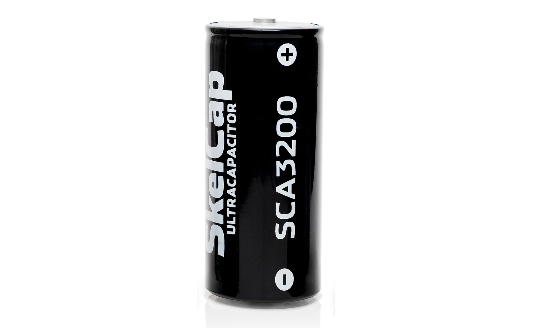
I really want Skeleton Technogies Ultra Caps, but there are no protections boards available for their termination.
I'm thinking of drilling a bit larger center hole in these protection boards to fit the Skeleton's:
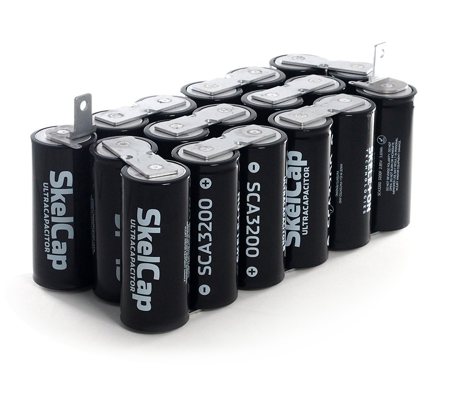
It looks like I just need to fill in a little bit of solder on top so it does not get loose, but it will be mostly flush. Soldering just on top of terminal tip, will not touch base.
I'm thinking of drilling a bit larger center hole in these protection boards to fit the Skeleton's:
It looks like I just need to fill in a little bit of solder on top so it does not get loose, but it will be mostly flush. Soldering just on top of terminal tip, will not touch base.
Last edited:
Yeah, you won't be able to solder those. those buss-bars are spot-welded on, not soldered (confirmed in the Skelcap datasheet). The cap cases are aluminium, as expected, thus not easily solderable (at least not with regular materials and equipment). I would expect the heat created by soldering to damage the cap, vs spot welding, which is hot, but quick vs soldering and I expect that is why welding is the only process called out in the datasheet.
- Home
- Amplifiers
- Power Supplies
- Develop ultra capacitor power supply and LiFePO4 battery power supply