Now it turns even more crazy.
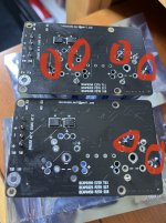
This is a UcPure in 15V configuration with 6*3000F ultracapacitors.
When powered on, only the fully charged ultracapacitor pack will be applied to the load. It will be a pure UC power supply and 100% isolated from any rest of the circuit.
No doubt this is the best 15V power supply in the real world. And it will be the best power supply for Andrea’s TWTMC clocks.
Why?
Actually ultra capacitor has two different working modes.
UcPure works in the first mode which I call it the class A mode. In this mode, only ultracapacitors apply to the load. No other active power supply is involved. The current goes only one direction out of the ultracapacitors into the load. Class A mode will ensure the best low ESR and low noise performance.
Another mode I call it the class B mode. In this mode, ultracapacitors work as class B shunt elements in parallel with another power supply or charger. The current goes both directions into and out of the ultracapacitor. Though the performance of this mode is still better than other active power supplies, but the dynamic ESR will still be higher than the class A mode because the ultracapacitor current crosses zero frequently. And even more, the noise of the power supply that attached can still be introduced into the voltage rail to make noise performance worse than the class A mode.
The sound quality difference between class A and class B can be heard clearly if we use them as power supplies for clock circuits such as the FifoPi clean side or the TWTMC oscillators.
UcPure is a heavy duty design for a durable operation. It can use both AC and DC as input. The quality of the input doesn't matter because the input will be disabled when UcPure is turned on.
Ian
A pair of these would nicely power a TDA1541 😀
Nice stuff. When the time is there, count me in! 🙂
I'm wondering how much of the SQ improvement with UCPure comes from the extra isolation and how much comes from the fact that the 3000F Maxwells have smaller ESR w.r.t. to the 300F Maxwells. (Sorry if this is already answered somewhere in the thread).
B.t.w. just installed UCHybrids on the rails for DAC and Fifo/Reclock. Very much impressed. I recognize similar SQ improvements as I experienced with small ultracap experiments in the past on a Digione Signature, but this is next level.
Hello,
A few minutes ago i had the UcHybrid board in my hand because i wanna make a kind of aluminium '' mainframe '' that will hold the lifepo4 board, the stationpi plus attached boards, one 5 volt UcConditioner for the raspberry and 3 Uchybrid boards .
3000F will have better specs than the ones i am using for sure.
There is the soldering contact that holds a terminal on both lifepo4 and UcHybrid board.
On both sides there is a contact between male and female connector
On both sides there is a contact between plug and cable.
Because every board will be securely kept in position i can use a two? inch cable directly soldered to the board. It wont turn my '' small '' cap into a 3000F cap but it will give me some benefit at no cost!
Greetings, Eduard
Thanks. D6 on two 5V boards are now lighting up. The power supplies measure at 5v. Should I not use the board until the light is off?
@stew1234
Seems the ultra capacitors were not fully empty. Can you measure the voltages of the two UCs?
It's better wait for the light going off.
Regards,
Ian
Seems the ultra capacitors were not fully empty. Can you measure the voltages of the two UCs?
It's better wait for the light going off.
Regards,
Ian
These are boards I've used before without issue. There are two 5v boards. On the first, one ultrcap is approx. 2.61v and the other ultracap is 2.19v. On the second 5v board, one ultracap is 2.63v and the other is 2.31v.
I also have a Salas ultrabib shunt reg. feeding another 5v ultracap board. In the past, it maintained 5v and powered the ultracaps without issue. Now, after I set it to 5v output and then connect the ultracap board, it won't get higher than about 4.77v. The only change was adding an additional 3.3v. ultracap board between the reclocker and the power supply (so completely different part of the circuit).
Any ideas what might be the issue?
I will try reconnecting everything as that solved som weird voltage issues in the past, including the over-voltage lights coming on.
Last edited:
Hey Stew1234, long time! Hoping you are good and staying healthy!
Are these new UCs from a commercial outlet? I've read about others seeing issues when using surplus/used UCs or buying them from discount sources.
Same with LiFePO4 cells.
Greg in Mississippi
Are these new UCs from a commercial outlet? I've read about others seeing issues when using surplus/used UCs or buying them from discount sources.
Same with LiFePO4 cells.
Greg in Mississippi
@jmmbarco
Yes, BCAP0350 P270 S18 works with UcConditioner.
For UcConditioner II 3.3V, you can mount them directly.
For other version, it can be mounted at back side of PCB.
Regards,
Ian
Yes, BCAP0350 P270 S18 works with UcConditioner.
For UcConditioner II 3.3V, you can mount them directly.
For other version, it can be mounted at back side of PCB.
Regards,
Ian
These are boards I've used before without issue. There are two 5v boards. On the first, one ultrcap is approx. 2.61v and the other ultracap is 2.19v. On the second 5v board, one ultracap is 2.63v and the other is 2.31v.
Hi Stew,
I have the same problem for a long time with the 5v version .. for some unknow reason, one of the two supercaps is discharged faster. therefore, an unbalance occurs, and if you do not turn it off in time, there will be an explosion risk.
Here is the link with prove IanCanada UltraCapacitor 5v disbalance problem - YouTube
You can manually discharge one of the ultra capacitors by a 10ohm power resistor until the voltages get equal. If the problem is still, then you have to make sure if the two ultra capacitors have the same capacitance or same leakage current.
Ian
Ian
Thanks for the input all. I hadn't used the DAC in a while and after letting everything settle while turned on the ultracaps appear to have equalized. All of the caps were purchased through Mouser so I would expect them to be new. I'll see how they behave going forward.
Ian, thanks for the reply
balancing with a resistor is not a solution, it is too difficult to remove and discharge each time.
there is another way. imbalance is guaranteed to occur if ucs are not turned on for more than 3-4 days.
so i do like this.
I turned it on and waiting for the overvoltage led to light up, then I turn it off. after 10 minutes I turn it on again, waiting for the led and turn it off. and so on average 3-6 times, depending on the degree of imbalance.
And the same, all of the ucs were purchased through Mouser.
Ian,
is it possible to mod 5v board, and when the led lights up, turn off or put the board into emergency mode/bypass mode?
because sooner or later someone will explode or catch fire if the board will be in a closed case.
is it possible to mod 5v board, and when the led lights up, turn off or put the board into emergency mode/bypass mode?
because sooner or later someone will explode or catch fire if the board will be in a closed case.
@alecm,
I have two UcConditioners (5V) in my system. I use them everyday and never had a problem. Ucs were also bought from Mouser.
Only for one time I had one red LED lit when I installed two brand new ultra capacitors. But after three hours of powering, the red light was gone. That's what the balancers work for (the voltage of the other ultra capacitor will be increased slowly to reach the balance point).
To evaluate the potential risk, I did a test to charge a 2.7V ultra capacitor to 3.5V. The only thing I've noticed was that the leakage current was increased. When the charger removed, the voltage dropped back to around 2.5V very fast in a couple of hours. Much faster than just charge it to 2.7V. This feature also tend to make the ultra capacitor with higher voltage back to the balance point rather than going to the other direction.
That's my own experiences, just hope some helps.
Regards,
Ian
- Home
- Amplifiers
- Power Supplies
- Develop ultra capacitor power supply and LiFePO4 battery power supply