Hello,
I am not sure if i understand the idea behind this.
BUT i think you will be able to use a very similar 3D product to use 4 325F 2,7 volt caps on ONE board to actually create a 100% increase of the F number.
Are you willing to make a few that can be mounted on the 3,3 volt UcHybrid boards?
You can send me a pm if you are willing to do this. I think there will be more people interested if it wont have a bigger '' footprint '' than the actual print from Ian.
Greetings, Eduard
Dear Supersurfer,
Thanks very much for your reply.
Do I still need to short anything to get 3.3V in J1, J2 and J4 and 13V in J3?
Thanks in advance,
igor
Thanks very much for your reply.
Do I still need to short anything to get 3.3V in J1, J2 and J4 and 13V in J3?
Thanks in advance,
igor
Hi, everyone,
My name is Igor and I desperately need some help.
I bought Lifepo4 and 10 batteries of which I decided to use only 7.
My idea was to have 3.3V on J1, 3.3V on J2, 3.3V on J4 (by shorting TP11-12) and 13.2V on J3.
I have batteries in BT1,2,3,4,5,6,7 and no batteries in 8,9 and 10.
When I connect the rails to Ian's DAC (3 x 3.3V) and I/V STD Mk II (13.2V) music starts playing for 3 seconds and then in 3-5 seconds no music at all.
On the other hand, if the I/V is LL1544A, everything works perfectly (no 13.2V needed).
What did I do wrong?
All the very best with your projects,
Igor
@ Igor,
I/V STD needs two 13.2V rails, but you use only one.
Ian
My version is for a more compact placement in the case.
A trial version, the racks are 2.5 mm after the epoxy glued.
I can share a 3D model.
@AirAir
That's a very smart idea 😀
Thanks for sharing.
Ian
Hi, Ian,
Thanks for helping me.
Now I see. So both J3 and J4 should be 13.2V. Ok, then no shorting.
And then I only have J1 and J2 for 3.3V, but I need 3 x 3.3V for your DAC. Hmm.
Thanks for wasting time with me ;-) Appreciate it very much.
Best,
Igor
Thanks for helping me.
Now I see. So both J3 and J4 should be 13.2V. Ok, then no shorting.
And then I only have J1 and J2 for 3.3V, but I need 3 x 3.3V for your DAC. Hmm.
Thanks for wasting time with me ;-) Appreciate it very much.
Best,
Igor
Hello Ian,
I already asked him in a PM if he can make me some with some minor adjustment.
It will allow me to double the cap value
Looks better than your temporary solution for the lack of 325F caps.lol
Greetings, Eduard
I already asked him in a PM if he can make me some with some minor adjustment.
It will allow me to double the cap value
Looks better than your temporary solution for the lack of 325F caps.lol
Greetings, Eduard
Hello,
I just ordered parts in Canada.
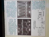
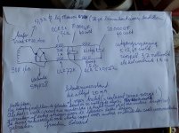
Because i need to order chokes anyway i decided to make an LCRC supply followed by an LM338 . Will use one for the LIfepo4 and one for a Roon nucleus.
The 350 mH 4A input choke will get rid of a lot of garbage coming out of the wall, the switching from the rectifier ( because there will be no switching) and the charging pulses.
With the Roon it will probably work both ways because it is full of switching supplies.
Psud will show a gentle rise of the voltage and a ripple close to 1 mV.
Some experts say that the amount of ripple isnt that important because of the regulator. It is more about things the choke can do and the regulator cannot.
Maybe in the lifepo4 it will be mainly the 5 volt supply that will profit because they lifepo4 could be disconnected from the charging circuit once they are '' full ''
The manual is not clear and Ian not answered . Can i create 3,3 volt each with two or more in parallel to give them a bigger energy level???
Greetings, Eduard
Hi Edurad,
I attached the schematics you sent me by email.
I think it's OK as the DC input of my LifePO4. But the only thing is that, when you turn on my LifePO4 power supply, all battery rails are disconnected from the input, so will be no business with the quality for the DC input. But still better than a switching mode power supply for reducing overall EMI noise into the environment.
Regards,
Ian
Attachments
@Ian,
In the 5V UcConditioner manual is states:
J5 ON/OFF Control Signal Output.
Would putting a jumper here effectively turn off the UcConditioner?
Right now I have an Allo Shanti LPS feeding the 5V UcConditioner that is powering my USBridge Signature. If the Allo Shanti is off for a while and the capacitors in the UcConditioner drain, then I have to manually disconnect the UcConditioner from the USBridge and wait for it to fully charge before connecting it again.
This is fine right now because all of these components are separate, but I have plans on putting everything in one larger enclosure and I don't want to have to open the enclosure every single time the UcConditioner is drained in case the Shanti is off if there is a power outage.
Ideally I'd like to mount a switch to the back of the enclosure that disconnects the UcConditioner from the USBridge Signature in the rare cases when the Shanti LPS is off for an extended period of time. This way I can plug the whole unit in with the switch in the off position while I wait 30 minutes (to be safe) before the UcConditioner is fully charged. Then I can turn the switch on and safely power the USBridge Signature.
I'd rather not add extra resistance or wire length between the output of the UcConditioner and the Rpi if I don't have to, so I'm wondering if I can control the UcConditioner by using the J5 option. Meaning, if the J5 is closed then the UcConditioner output is OFF and if J5 is in the default open position, then the UcConditioner is ON.
Please forgive my ignorance here, just trying to figure out the best way of going about this.
-Allen
Hello,
For those interested in using the Maxwell 325F 2,7 volt snap in caps i just received an update about my order.
Last time they expected to send them end of July first week of August.
NOW this has been changed into 13 OCTOBER so probably will order caps actually in stock.
Going up in F number is not difficult BUT if ESR is similar and in most cases even a bit higher than the 325 F will going up in F be better. NO i wont go up to 3000F because there is no room for that.
Greetings, Eduard
Hello,
Just a small but according to me important update. If you mount the caps like Doede did you have to take care about the diameter of the caps!
The maximum diameter you can mount on the UcHybrid board is 33 mm which is the diameter of the 325F Maxwell. If you search for 30 and 33 MM on the Mouser site an AVX will show up as being 30 mm but according to the manufacturers pdf it is 35 mm which wont fit.
The UcConditioner board has a TINY bit more space but i wouldnt take the risk.
Greetings, eduard
Hello,
When reading a thread i came across the info in the attachment.
In the pdf is the info about the 300F cap that could replace the 325F cap .
Of course 3000F is nice BUT then you should also pay more attention to wires and connectors.
Having a threaded M12 connection on the cap side and the typical terminal with a tiny M3 bolt looks a bit strange.
The caps being physically this big will make it different to put them close to where the power is needed.
That is the reason i went for a '' set up '' with 3 3,3 volt supplies each have its own UcHybrid board and each supplying a different element in the '' chain '' that needs 3,3 volts.
Dont know if supplying the 3 elements from the same lifepo4 cell with a set of 3000 F caps from an original dealer would be better.
Mutual influence will be lower with more F and/or less ESR.
If current being drawn by the 3 elements is very steady influence will be lower too but i think in real life there are not a lot of circuit that present a nice and steady load.
SO my idea is giving each element its proper cell will be better. Maybe later give the biggest '' consumer '' to coke can seize caps.
But will they mounted in the typical diy audio style with elastic bands and duct tape?
Greetings, Eduard
Attachments
Greetings everyone,
We have a holiday here in the US, going to fire up the soldering iron, get my 2 LifePO4 MkII boards connected up to my UcAdapter PCB's.
I'm looking for a photo of:
UcHybrid integrated with LifePO4 MkII through UcAdapter PCB.
Has anyone else done this one yet?
In the manual, Ian included a photo of the connection of the UcMateConditioner ON/OFF control signal from LifePO4 MkII power supply through UcAdapter PCB. But not the UcHybrid.
Thanks,
Aguaazul
Last edited:
Hello,
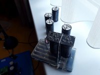
Just a small update . I just received the Skeleton caps i referred to in post 1471.
They fit exactly onto Ian's boards and they are made in Germany . A bit more expensive than the other ones but if built quality can predict sound they are perfect.
The French already performed test with caps in the eighties if they could turn them into a electrostatic '' speaker '' by causing parts inside the cap to vibrate. Because vibration specs are often mentioned in supercap datasheets this could well be something that needs some care. The Skeleton cap has 4 soldering pins just like the Maxwell. But the Maxwell just uses two as a terminal and the other two for securing .
The Skeleton has a '' center '' connection for the negative terminal and 3 pins for the plus .
Greetings, eduard
Greetings everyone,
We have a holiday here in the US, going to fire up the soldering iron, get my 2 LifePO4 MkII boards connected up to my UcAdapter PCB's.
I'm looking for a photo of:
UcHybrid integrated with LifePO4 MkII through UcAdapter PCB.
Has anyone else done this one yet?
In the manual, Ian included a photo of the connection of the UcMateConditioner ON/OFF control signal from LifePO4 MkII power supply through UcAdapter PCB. But not the UcHybrid.
Thanks,
Aguaazul
Please watch this video:
The Best Sound Quality Audiophile DIY DAC I Built in 2020 - YouTube
Ian
Thanks Ian. I have LifePO4 MkII boards. In your video I see the LifePO4 MkIII boards.
Is there a schematic of the connections for the MKII / MKIII & the UcHybrid - UcMateConditioner connections?
Thanks,
Aguaazul
Hello,
Just soldered the first pair of German supercaps to a 3,3 volt UcHybrid board. I held the caps and board in position with an elastic because you dont want them to move during soldering and during cooling down. As you can see the contact area for the plus side is BIG so heat will be transferred from the soldering spot quickly. So must take care of a firm contact on the soldering spot to reduce the change of a bad joint because of to low temperature. The soldering " area " is just a tiny ring to a bit difficult to get maximum heat transfer.
I think that there will be bad soldering joints around when not enough wattage is available needed for the supercaps.
Greetings,Eduard
Attachments
What is the part number for these cap? I assume they're working without issue? If they're not available in the US, I'll try Ian's larger solution.
I understand that the ultra-capacitors are now having very long lead time under this COVID situation.
But just found the new MAXWELL 450F BCAP0450 P270 S18 ultra-capacitors are still keep in stock. This ultra-capacitor will be great to work with my UcConditioner. But the footprint is different.
Now I have solution to mount them to my UcConditioner.
1. Bent the two NC pins and then cover with tape to avoid any possible short circuit.
2. Solder the two 450F UCs to the UcConditioner at the bottom side of the UcConditioner PCB.
3. Make sure + and - are at correct positions.
Please refer the attached pictures for details. Please let me know if you have any questions.
If it is required, you can disassemble the input/output terminal block connectors and then flip/solder them to the other side of PCB.
Good weekend.
Ian
Ian, if going this route, is there any reason not to break the tabs off of the two taped contacts and then tape over as well to reduce the risk of a short?
Hello,What is the part number for these cap? I assume they're working without issue? If they're not available in the US, I'll try Ian's larger solution.
They are available at Mouser. The datasheet is in post 1471.
But you need a powerful soldering gear.
Greetings, Eduard.
P.s i am happy i went for this solution.
- Home
- Amplifiers
- Power Supplies
- Develop ultra capacitor power supply and LiFePO4 battery power supply