that was just and example sir, even if you have 10 pairs you only need to read one of the emitter resistors to adj bias, the supply will be I'm guessing that you are using from 65V DC to 75V DC right? 10 pairs will drain a lot of current be careful with thermal runaways, are you using one of Carlos's design as an IPS driver board sir ? oh yes better check those $11 bucks semiconductors they might be fake "falsos" as Andrew mention check them before anything else
I was just meaning to have backups - not using more than 1 pair. How would you use more to enable a higher voltage supply?
if you have 2 pairs you can go with 45V to 50V more or less, if you add more pairs you can add even more voltage having more pair will also help to dissipate all that heat throughout all of those semiconductors output pairs they will share all that current between them therefore less heat " that is what I think" I might be wrong
Regards
Juan
Regards
Juan
Attachments
Has anyone on this thread doubled up (or more) the main power transistors successfully? Do I just need emitter resistors to separate them and also have added 4.7k resistors to the gates from common?
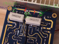
It's very strange. I installed emitter resistors (0.33R) between the emitter and the speaker out for each side. I cut the trace on the board. I measure 0.000v! (good Fluke DMM) across either of the resistors when trying to set the bias current using emitter resistor for current measurement. But if I use the external 10R resistors, I get 100mV (and it changes when I adjust the pot). However, the external current as measured with the 10R resistor cannot go above 180mV. It plays music. It is absolutely cool at normal volumes and barely warm when I am playing loud. So is this a case of things just not operating correctly due to the +/- 20v power supply?
It's very strange. I installed emitter resistors (0.33R) between the emitter and the speaker out for each side. I cut the trace on the board. I measure 0.000v! (good Fluke DMM) across either of the resistors when trying to set the bias current using emitter resistor for current measurement. But if I use the external 10R resistors, I get 100mV (and it changes when I adjust the pot). However, the external current as measured with the 10R resistor cannot go above 180mV. It plays music. It is absolutely cool at normal volumes and barely warm when I am playing loud. So is this a case of things just not operating correctly due to the +/- 20v power supply?
hello sir can you post images ?
hello sir can you post images ?
Please call my X or Xrk... 🙂
I verified that the cuts to the PCB traces were good with ohm meter prior to soldering 0.33R's.
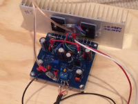
Here are some images:
Attachments
Last edited:
it will help if you also post the schematic too mister Xrk 🙂Please call my X or Xrk... 🙂
I verified that the cuts to the PCB traces were good with ohm meter prior to soldering 0.33R's.
Here are some images:
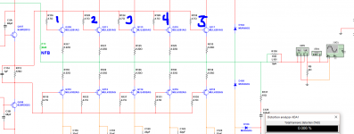
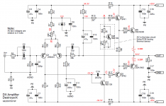
that circuit is class AB or class A ?
it will help if you also post the schematic too mister Xrk 🙂
that circuit is class AB or class A ?
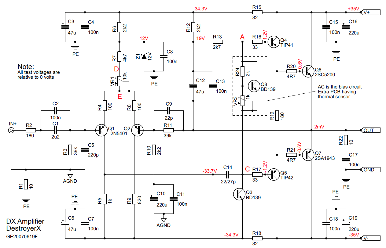
This is the Dx amp thread is t it? It's the same as the one on Greg's website:
Attachments

This is the Dx amp thread is t it? It's the same as the one on Greg's website:
did you see Carlos's annotation ? maybe this will help 🙂
Attachments

This still doesn't explain why I have zero volts from emitter to common out when 0.33R replaces wire from emitter to OUT. I am running +/-20v. Does that make a difference?

are you reading voltage drop from the emitters right ? mV
Yes.
Member
Joined 2009
Paid Member
If I understand correctly you have the following facts:
a) you have measured current flow through the amplifier of up to 180mA and you can adjust it using the potentiometer designed to affect the output pair bias current
b) you have measured close-to-zero voltage drop across one of the output device emitter resistors. Unless this resistor is shorted somewhere (did you measure the resistance between output and power device emitter leads?) there isn't any current.
So, since current must flow in a loop I can think of two possibilities
i) the current you measure flowing through the power rails is not flowing through the output devices but some other route through the circuit. This seems unlikely to me.
ii) the current is flowing only through one output device, the one you did NOT measure the emitter resistor voltage drop across and this current completes it's circuit through the load. This can only be the case if you have a load connected to the output. To test for this, disconnect the load and look to see a dc-offset at the output. Also, measure the voltage drop across both emitter resistors in series, i.e. from emitter to emitter.
Maybe there are other explanations ?
If I understand correctly you have the following facts:
a) you have measured current flow through the amplifier of up to 180mA and you can adjust it using the potentiometer designed to affect the output pair bias current
YES - and this is with external 10R resistors in series with the power supply leads per the recommended setup instructions for the Dx amp on the website
b) you have measured close-to-zero voltage drop across one of the output device emitter resistors. Unless this resistor is shorted somewhere (did you measure the resistance between output and power device emitter leads?) there isn't any current.
With no power connected, the resistance between the output pin and emitter leads measures the same as the bare resistor (0.323 and 0.321 ohms as measured with my DATS v2 RLC meter - the Fluke is not as accurate at low R's like that).
So, since current must flow in a loop I can think of two possibilities
i) the current you measure flowing through the power rails is not flowing through the output devices but some other route through the circuit. This seems unlikely to me.
Where else would it go?
ii) the current is flowing only through one output device, the one you did NOT measure the emitter resistor voltage drop across and this current completes it's circuit through the load. This can only be the case if you have a load connected to the output. To test for this, disconnect the load and look to see a dc-offset at the output. Also, measure the voltage drop across both emitter resistors in series, i.e. from emitter to emitter.
I measured it through both emitter resistors, and they are both at zero volts. I had the DC offset adjusted to be precisely 0mV (the VR1 10k offset pot works - it affects the offset and I can control it). The voltage from emitter to emitter is still 0.000v. While measuring the voltage from output to emitter, changing the offset pot has no effect on the voltage - and this is strange as I would have thought that would have done it.
All I can think to do is to break the trace on the second amp and install resistors there too and re-measure.
Maybe there are other explanations ?
One thing to note is I am running at +/-20v rails. Does that make a difference? And note that the amp plays music rather nicely with the 20v rails. I even hooked up a high power sub driver and made it exercise its muscle - it definitely can make sound and move air.There is a little harshness in the treble - I am told indicative of a low bias (which I guess causes zero crossover distortion). it'st not bad sounding though.
Here is how I installed the resistors just to be clear.

Attachments
Last edited:
Post 7477 pic:
take off the voltage measurements for the ±37Vdc supply rails and insert your measurements with the ±20Vdc supply rails.
Include measurements across the input LTP and the input offset voltage.
take off the voltage measurements for the ±37Vdc supply rails and insert your measurements with the ±20Vdc supply rails.
Include measurements across the input LTP and the input offset voltage.
AndrewT, appreciate your willingness to help de-bug this. I will probe the circuit when I get home tonight and report back.
Thanks,
X
Thanks,
X
One thing to note is I am running at +/-20v rails. Does that make a difference? And note that the amp plays music rather nicely with the 20v rails. I even hooked up a high power sub driver and made it exercise its muscle - it definitely can make sound and move air.There is a little harshness in the treble - I am told indicative of a low bias (which I guess causes zero crossover distortion). it'st not bad sounding though.
Here is how I installed the resistors just to be clear.
Hi xrk971,
Circuits that use resistors to set the current are designed to work at a particular voltage. So it will probably still work, but you have effectively halved the current flow. V=IR => I=V/R
regards
- Status
- Not open for further replies.
- Home
- Amplifiers
- Solid State
- Destroyer x Amplifier...Dx amp...my amplifier