Member
Joined 2009
Paid Member
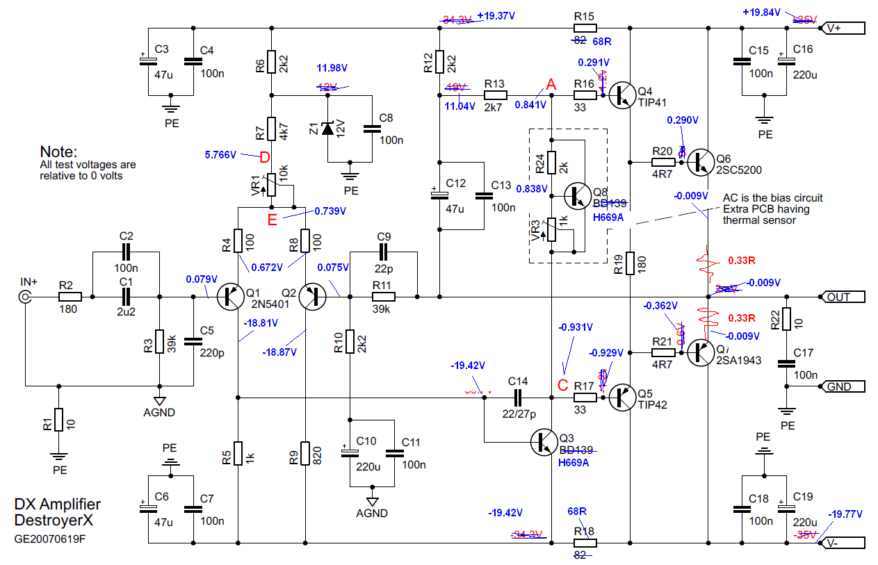
For lower rail voltage R12 and R13 will need to be scaled down in proportion to provide the required current for the VAS stage (Q3). This may prompt you to increase C12 to 100uF.
And R6 should also be reduced so that the zener regulator for the LTP has enough current. It's more usual also to see a cap across the Vbe multiplier (points A and C) but Carlos may have had reasons not to.
And R6 should also be reduced so that the zener regulator for the LTP has enough current. It's more usual also to see a cap across the Vbe multiplier (points A and C) but Carlos may have had reasons not to.
Last edited:
Post 7477 pic:
take off the voltage measurements for the ±37Vdc supply rails and insert your measurements with the ±20Vdc supply rails.
Include measurements across the input LTP and the input offset voltage.
Here are the test point measurements you requested. This is with inputs shorted and no load of course.
Thanks!
Attachments
Calculate the currents through R4, 5, 8 & 9 check how well balanced the LTP is.
All the Vbe around the LTP look OK. Note the input offset voltage = +79mVdc. This is normal for a PNP LTP.
But the balance of emitter voltage does not agree with the imbalance of the collector voltage. Did you match 100r? Did you match Q1 to Q2?
Something wrong with the -19.42Vdc shown at the base and emitter of Q3
Q3 is the wrong device for the second stage.
Calculate the currents passing R12, 13 & 24
Calculate the Ic of Q8
Vbe of Q8, OK, but Q4 shows zero !!!!!
Vr19 missing. When the second stage is working properly with the correct current then Voltage A to B is the bias voltage. When the output stage is turned on Vab is ~2.3V
and Vr19 is ~1.2V
When you start up with the bias voltage turned right down, Vab <1V and Vr19 ~zero
Calculate current passing R16 & 17. That's the base currents of the driver stage. Something wrong.
Calculate the output base currents.
Calculate current passing R15 & 18. That's your front end quiescent current.
It is the currents and Vbe that are important.
I recommend you change R2 to nearer 1k and/or increase C5 to 1nF
Last edited:
AndrewT,
Thanks for the detailed analysis. I will have to get that Vr19 for you. I wonder if the problem is the incorrect transistor, but I have to wait until I get a 35v power supply to see if it makes a difference.
Thanks for the detailed analysis. I will have to get that Vr19 for you. I wonder if the problem is the incorrect transistor, but I have to wait until I get a 35v power supply to see if it makes a difference.
I'd say -19.42Vdc on base of Q3 is a typo as on the same net there is -18.81V which looks right.
I'd say -19.42Vdc on base of Q3 is a typo as on the same net there is -18.81V which looks right.
Thanks, good catch. Do you have an opinion of suitability of the H669 transistor substitution for BD139?
I don't have much useful data for 139, so I can't assess it's suitablity for VAS.
You should be using a highish gain, that is fairly linear, ultra low Cob and preferably a high Early voltage (Vaf)
a1360/c3423 does this job
A d669 is a very good driver, if it meets the Hitachi specification.
You should be using a highish gain, that is fairly linear, ultra low Cob and preferably a high Early voltage (Vaf)
a1360/c3423 does this job
A d669 is a very good driver, if it meets the Hitachi specification.
Last edited:
Thank you all....very kind from the major part of you
Excess amplifier was something surprising in my life.... a defect that become an effect...watch the waveform.....there's you see the secret....can you see a kind of "carrier".
This recording gave me a lot of work.....was made in separate this audio and them inserted to the video image (synchronism show you that)...i had used pillows, mattresses and some small carpet to build a chamber in front of the speaker and them to place the microphone....then i reproduced the audio and i found the WM61 Panasonic cartridge was increasing frequencies above 12k...i had to reduce using and equalizer..and then sounded the same when i put my ear in the hole used to insert the microphone, 1 meter distant from the speaker, 1 watt power output (peak)....then i made the audio insertion of the recording made using microphone pointed to my t-line speaker reproducing this audio sequence captured from "DIY auto school".
Finally i perceived the video playing with the same audio i was listening while recording...the real thing...without the high end excessive...the lovely distortion presented.
You see how "thick" is the waveform.....inside you have a carrier...this is the trick..... was hard to produce the lovely defect.
Here you have a sample...... visit heaven folks, as i cannot believe someone can make the sound better than the original...the maximum is to be the same...this one is the same...has all the magic..without the losses of mic recording, home acoustics and so on...but a lot of work..speaker over foam...hard work....foam matress covering wall...something ugly and ridiculous.... an acoustic chamber.
54 seconds video sequence...so....even if you have a slow internet speed will be able to listen.
https://www.youtube.com/watch?v=u4tGBiqMnzQ
regards,
Carlos
Last edited:
destroyer X,
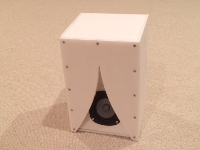
Thank you for posting that video clip with a good sound quality recording. I just listened to it on my Dx amp playing through a transmission line full range speaker and it sounds great. It looks like you have some sort of TL speaker as well - nice clean bass. I often make recordings of my speakers using a digital recorder (Zoom H4) and upload the 320kbit mp3 file as an attachment renamed with the .asc extension. This allows you to have as large as a 1.8Mb file size (45 seconds long at 320kbit). I must have hundreds of uploaded sound clips to go with all my speaker builds by now. Here is the speaker I just listened to your video with - it's not the flattest response, but is very musical and rich full bass for a 4in driver.
Here is a sample soundclip from the speaker I just used to listen to your clip:
http://www.diyaudio.com/forums/atta...444881377-improving-chn-70-chn70-knator-2.asc
Rename the file to .mp3 extension to listen.
Thanks for sharing your nice video with high quality sound and thanks for giving us such a wonderful amplifier to listen to music with.
Regards,
xrk971
I am glad to know that.
Yes, i am using a T-line speaker...the ones i love the must (link in the signature line)
I am still trying to convert your link to mp3...will ask some help
from my job IT experts.
regards,
Carlos
Yes, i am using a T-line speaker...the ones i love the must (link in the signature line)
I am still trying to convert your link to mp3...will ask some help
from my job IT experts.
regards,
Carlos
Last edited:
Rename the file from xxxxx.asc to xxxxx.mp3.
On a PC, after downloading - uses save file option. Then in Windows Explorer (file manager) click on file name to get cursor focus. Then wait 1 second and click again to get to change file name mode. Or right click and select "rename". I think on a Mac, hold down the special function button while clicking file then select rename. It is an MP3 file just that the extension has been renamed to .asc to trick the server into letting me upload something bigger than 760k.
On a PC, after downloading - uses save file option. Then in Windows Explorer (file manager) click on file name to get cursor focus. Then wait 1 second and click again to get to change file name mode. Or right click and select "rename". I think on a Mac, hold down the special function button while clicking file then select rename. It is an MP3 file just that the extension has been renamed to .asc to trick the server into letting me upload something bigger than 760k.
Thank you...much easier than i though.
I have listened....nice one...thank you.
The bass is the sonic signature....i can recognize the amplifier.🙂
regards,
Carlos
I have listened....nice one...thank you.
The bass is the sonic signature....i can recognize the amplifier.🙂
regards,
Carlos
If you like the sound of that speaker - they are very easy to make and have so much rich full bass that they are the only speakers I know of that don't require baffle step compensation when away from walls.
More here: http://www.diyaudio.com/forums/full-range/239338-mini-karlsonator-0-53x-dual-tc9fds.html
The full size one uses a 12in driver. I use Akabak model to resize for smaller drivers.
More here: http://www.diyaudio.com/forums/full-range/239338-mini-karlsonator-0-53x-dual-tc9fds.html
The full size one uses a 12in driver. I use Akabak model to resize for smaller drivers.
Thanks, good catch. Do you have an opinion of suitability of the H669 transistor substitution for BD139?
If you're still looking for debugging help with your schematic, everything looks fine except for the voltages around the H669A bias spreader. Its not generating enough voltage to bias your OPS. Could there be a faulty transistor or an error in its pinout? You have 1.7V between B and E which either means its blown or its pins have gotten swapped.
If you're still looking for debugging help with your schematic, everything looks fine except for the voltages around the H669A bias spreader. Its not generating enough voltage to bias your OPS. Could there be a faulty transistor or an error in its pinout? You have 1.7V between B and E which either means its blown or its pins have gotten swapped.
Thanks for the tip, let me try swapping that with a fresh one. I will also check the pinouts. On another note, I just finished debugging my Pass ACA amp. It's working now and sounds very nice. Problem turned out to be an error on the pdf diagram of the PCB trace layout. I used that to wire my PTP board and the pot is connected to the wrong cap in the drawing.
ou have 1.7V between B and E which either means its blown or its pins have gotten swapped
What should I be measuring?
Q8 - the one with the preset pot next to it.
Incidentally I recently bought a bag of 2SD669As and found they weren't at all consistent between samples. Not sure if they were fakes but I gave up on designing with them. The H669A looks to be electrically the same but from another manufacturer. I think mine said Hitachi.
Incidentally I recently bought a bag of 2SD669As and found they weren't at all consistent between samples. Not sure if they were fakes but I gave up on designing with them. The H669A looks to be electrically the same but from another manufacturer. I think mine said Hitachi.
I have tested these transistors, not only 2SD669A but also MJE340/350
Sound was a little bit better in highs..... or.... i convinced myself that was better without make A/B comparison.
A lot of ideas colapsed to ground when i made A to B comparison....blinded ones, because other methods are fool in methods.....just serve to ourselves to reinforce hypothesis we have created to support our own beliefs.... when we make A to B, real stuff appear.... reality becomes something you cannnot doubt.
These transistors, and many others, finished died, shorted, damaged, after my traditional torture tests.... i do not have them anymore.....so..... they died.
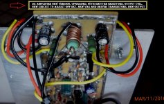
MJE340/350 also died...but i keep one pair when i have my own doubts..then i install as VAS in one channel to compare with the second channel....and then i realise, again and again, and once more, and twice, that BD139/140 are unbeatable into this range of supply voltage..... TIP41/42 really deserves to be replaced...but BD139 entered my amplifiers to stay.
Never believe in thoughs.....never believe in faith...... test all your ideas...do comparison tests and you will be surprised how much we can fail related our pre conceived ideas.
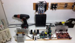
Photo show you the "Comparator"..... make something alike and you gonna be surprised with your conclusions...same signal entering...all amplifiers adjusted to the same sensitivity...same speaker....then ask someone to operate the rotaring switch and take note about your conclusions..... operator will give you numbers and will correlate these numbers with the switch...from 1 to 6.....you will not know what amplifier is playing as he will give you scrambled numbers..not the real sequence..nor the inverted sequence.....if i was not clear.... he can rename 1,2,3,4,5 and 6 as 4,2,6,1,3,5 .... this way you have not idea what is playing even considering you have built the comparator.... use a clever operator not to switch in sequence...or you will realise what is going on..... understand, in advance, that you are clever and you will try to discover all time long what is playing...this is human nature.
Do it...... and you will see the reality in a different way .... and will not trust your pre conceived ideas anymore.
One audio source, several types of songs, one output speaker (at a time), same output power to all amplifiers...same conditions.... a fair comparison.... you cannot know what is playing...instruct switch operator not to modulate voice according to his taste....ask him to be monotone...dark room...listen to speaker and small ligth into your portable annotation book.
regards,
Carlos
Sound was a little bit better in highs..... or.... i convinced myself that was better without make A/B comparison.
A lot of ideas colapsed to ground when i made A to B comparison....blinded ones, because other methods are fool in methods.....just serve to ourselves to reinforce hypothesis we have created to support our own beliefs.... when we make A to B, real stuff appear.... reality becomes something you cannnot doubt.
These transistors, and many others, finished died, shorted, damaged, after my traditional torture tests.... i do not have them anymore.....so..... they died.
MJE340/350 also died...but i keep one pair when i have my own doubts..then i install as VAS in one channel to compare with the second channel....and then i realise, again and again, and once more, and twice, that BD139/140 are unbeatable into this range of supply voltage..... TIP41/42 really deserves to be replaced...but BD139 entered my amplifiers to stay.
Never believe in thoughs.....never believe in faith...... test all your ideas...do comparison tests and you will be surprised how much we can fail related our pre conceived ideas.
Photo show you the "Comparator"..... make something alike and you gonna be surprised with your conclusions...same signal entering...all amplifiers adjusted to the same sensitivity...same speaker....then ask someone to operate the rotaring switch and take note about your conclusions..... operator will give you numbers and will correlate these numbers with the switch...from 1 to 6.....you will not know what amplifier is playing as he will give you scrambled numbers..not the real sequence..nor the inverted sequence.....if i was not clear.... he can rename 1,2,3,4,5 and 6 as 4,2,6,1,3,5 .... this way you have not idea what is playing even considering you have built the comparator.... use a clever operator not to switch in sequence...or you will realise what is going on..... understand, in advance, that you are clever and you will try to discover all time long what is playing...this is human nature.
Do it...... and you will see the reality in a different way .... and will not trust your pre conceived ideas anymore.
One audio source, several types of songs, one output speaker (at a time), same output power to all amplifiers...same conditions.... a fair comparison.... you cannot know what is playing...instruct switch operator not to modulate voice according to his taste....ask him to be monotone...dark room...listen to speaker and small ligth into your portable annotation book.
regards,
Carlos
Attachments


Last edited:

- Status
- Not open for further replies.
- Home
- Amplifiers
- Solid State
- Destroyer x Amplifier...Dx amp...my amplifier