That modification i have asked to Greg, moved the output coil to a nearest point
related the input...this was not so clever..but i did that.
The result is that distances turns smaller, and magnetic field change enormously the intensity depending the distance.
observe the coil position.
regards,
Carlos
related the input...this was not so clever..but i did that.
The result is that distances turns smaller, and magnetic field change enormously the intensity depending the distance.
observe the coil position.
regards,
Carlos
Attachments
Sorry, dear Greg, that i have asked you this foolish.
Better to run wires directly from the output line to the speaker Klass...using this coil or trying without it.
Remove the coil from it's board place...not to interfere.
I will not be too much surprised if this noise over the clipping will disappear completelly.
I am sorry to say that there are a lot of good designers doing this foolish too.... this connects me with them.... at least we have something common that turns me better...aligned with them...hehe.
regards,
Carlos
Attachments
For sure magnetic fields are there, and they may turn AC voltage when crossing
transistor leads.... that signal will interfere..for sure.
I think it can be a source of the problem...if not...it is wrong there.
I will ask you Klass, and all guys, to remove this coil from there and install in another place, distant from the input and from the feedback transistor Base.
I apologize..even if we conclude as not beeing the source of the problem..i apologize to all you forum friends..this is very wrong...was a big stupidity from me.
regards,
Carlos
Attachments

Hi Klaas,
I thought it odd that you had instability at low voltage, but you then said the scope input was reversed.
Thus you had instability when the current in the VAS was low and its voltage high giving lower internal C with heightened gain; oscillation when the VAS collector voltage is high is a known problem.
I can only echo Carlos' recommendations in his posts #351 and #359.
Good luck ......... Graham.
Thanks Graham... a corrections is needed into post 351
Capacitor is from base to colector.... but from base to ground can work too.
regards,
Carlos
Capacitor is from base to colector.... but from base to ground can work too.
regards,
Carlos
Observe Klaas, how Sansui was carefull to avoid unstabilities.
This is a professional...a comercial amplifier...so...people not able to tweak.... enormous quantity of protections against unstability that will create sonic problems too.
We can do the same...facing unstabilities and them we can go removing till the unstability happens once more...so...we will conclude the minimum possible capacitors to install, and the better point to install them.
We have the advantage to remove excesses of weigth and turn the amplifier sligtly better in sonics related the factories, as they cannot sell something that will be near the threshold of oscilation.
We can decide.... how distant we want to be related oscilations...the more stable the amplifier...normally sonically they loose for the less stable ones (the same amplifier modified reducing capacitors)...because all those compensations you can see, in red, marked over the schematic.
regards,
Carlos
Attachments
This morning, after getting rid of the construction-workers inside my head trying to rearrange my neural pathways (Dutch parties usually envolve beer) i have tried some of your suggestions.
Before doing so, i reversed some changes made previously.
Output-coil removed.
Zobel-resistor changed back from 5r to 10r.
Re-installed rail-fuses for safety.
I took some notes:
- moved the speaker-output to junction on pcb between op-devices. The only currents running across the pcb (that could cause problems ) are now feedback-current and zobel-current.
No improvement.
- increase feedback-cap from 12 pF to 24 pF:No improvement.
- Miller-cap increased from 12 to 24 pF: No improvement.
- 12 pF across base-collector of drivers: slight improvement, but still oscillation before clipping. 22 pF gave same result.
- 22 pF across base-collector of outputs: same result as caps across drivers.
- put cap 1nF across base-collector of feedback-transistor.
Sine-wave is clean now until clipping at ~ 60 volts pk-pk giving 67 watts into 6.75r.
Still some nasties occur at clipping at the trailing edge of the top of the sine-wave. 1 khz sine looks the same.
Looks like improvement to me, so you don't have to order that shuttle-ticket just yet Carlos 😀
Best regards,
Klaas
We use beer too.... i will use some because of those nasty things.
There are more possible modifications, observe the Sansui schematic posted and the red rectangles...you can see some tweaks in the input.... capacitors over the output transistors too.
And try, once again, the zobel...now reduced to 2R2 ohms.
SORRY, correct capacitor is from base to emitter in the feedback transistors..that one pointed to the output line.
This will be a low impedance load for high frequencies...hummm...will eat that thing i suppose.
My imagination is that you have some experience with your scope...that you have used it before without any problems...this question is made to delete the scope from my suspections.
Also i will be happy to know if you have installed wire, as antenna in the scope input....just to observe possible signals present around your home.
I have already blame the Scope...now i will blame the town..too much humidity...ahahahaha...kidding.
regards,
Carlos
Those tweaks are to finish with the clipping unstability
Having a clear waveform when clipping..nothing over the clipping time line...start to remove capacitors installed.
So.... modifications have to be removed, one by one watching the scope to conclude, the main one, that made a real difference.
This may be "the single one needed"...others can be removed.
Try also to use your big Beer Can electrolitic condensers once again, as you are using 2200uf.
regards,
Carlos
Attachments
Well i'm done soldering for today i guess 🙂
I've tried most caps you mentioned, most of them seem to have almost no influence.
The only things that worked were the cap across base/collector of the feedback-transistor, and increasing c5 (bandwidth-limiting of input) to 1nF.
We'll see tomorrow...
with kind regards,
Klaas
I've tried most caps you mentioned, most of them seem to have almost no influence.
The only things that worked were the cap across base/collector of the feedback-transistor, and increasing c5 (bandwidth-limiting of input) to 1nF.
We'll see tomorrow...
with kind regards,
Klaas
Try base to emitter Klass
If this 102 is working, the interference is in the air....have you tested the antenna...the aerial into the scope input.
Have you checked your scope with aerial and without it to see scope stability?
I have forced to create unstabilities in my home and i could not make the same you have...even trying....very interesting that.
Also i have replaced my transistor for a higher speed version and i could not see that unstability during the clipping time line....well...my scope is a PC scope.....maybe mine is not good.
Try, please, 102 or bigger, from base to emitter...the way Graham Maynard use in his amplifiers.
regard,
Carlos
Attachments
Hope you get it working, I'd like to start soon...
Didn't get any further than looking at the files... my one cat got sick and it turned out to be cancer, so we had to put her to sleep...yesterday, was very sad day, actualy we are not even close to being over it. My wife and I are very close to the "kids".
Didn't get any further than looking at the files... my one cat got sick and it turned out to be cancer, so we had to put her to sleep...yesterday, was very sad day, actualy we are not even close to being over it. My wife and I are very close to the "kids".
Sorry about your Cat..... i have lived something alike your experience with a dog.
To put it to sleep....was awfull.
Related the amplifier, it sounds nice the way it is...as only during clipping periods, and people normally do not listen clipping...exception may be some crazy people inside a dedicated hospital...when they love clipping, television advertising and Government taxes.
I could not produce the unstability here in my home, it is possible that migth be a local problem that will be discovered soon.
If not, the basic schematic will remain the same...maybe one bigger condenser here or there.....maybe one extra at the input or bigger miller one.....that's it.
If interested you can start...you will be happy...for sure.
We are searching for the problems and all stuff is finishing...so...it is very near to find the guilty.
regards,
Carlos
Thanks uncle Charlie...
I live next to a very low income area... on weekends every second house has an amp turned all he way up, and the spekers sounding like they tore loose from their baskets 10 years ago... all thats important to these people is that it is loud...If it ain't clipin' you ain't hipin.
I doubt we ever go much over 10Watts use in my house (very small)\
I have turned my amp up all the way a few times (the Mauro My_ref C), speakers rated for 140W, so I couldn't get it to distort! lol.
Hi Klaas,
I am still concerned with your choice of VAS and driver transistors.
It is better to use low C-bc devices with a small capacitor across the base-collector junction in order to reduce overall base-collector capacitance variation with V-ce.
It is also better to use genuine 120V to 200V devices at 80 to 100V in audio amplifiers.
Also what about trying a slightly lower value of base-emitter resistor for the VAS and increasing the differential tail current.
This is one of those situations where, if Carlos was advising over your shoulder and offering parts from his spares box, the problem would be sorted in moments.
(Question? Are you using a high impedance scope probe, or connecting up directly using plain coax ? Directly connected scope lead capacitance can cause spurious oscillations.)
Cheers ......... Graham.
Graham, on the probes, is it better to get hi-Z probes, I had a bit of good fortune and will be phoneing a local company who specialises in serviceing and reselling old scopes...tommorrow.
Hopeing to get something analog.
Hopeing to get something analog.
Sorry to hear about your cat, Nordic.
A long time ago my cat was ran over by a car, i had to bury it in the back-garden. I know the feeling..
Thanks for the suggestions, Carlos and Graham.
I'll have a go at it tomorrow, i'm done for today regarding electronics 🙂
There's lots of interference /airborne noise here ,dimmers , 1 laptop, 1 PC, switching powersupplies .
My probes are 1/10Mohms.
Best regards,
Klaas
Hi Nordic,
For general use it is better to have a proper probe than just using plain coax, as Klaas has clarified he is using.
Hi Klaas,
If your amplifier is picking up those interferences then there could be something not quite right with your amplifier wiring.
I trust your 'scope is isolated too.
Cheers .......... Graham.
Thanks Graham, as you have remembered other possibilities
Nordic.
Bad education is turning an Universal problem, i have noticed those things everywhere...people invading the next doors neighboor rigth to silence..this is very common here too.
There are many guys that install big amplifiers, with 600 to 700 hundred RMS watts, undistorted watts, from a 10 channels amplifiers...using switching power supply inside...pulse width modulation techniques.... sucking 80 amps from the batteries.
They use two batteries, or truck batteries.
They park their cars in front of the beach and polute with loud sound almost 400 meters in diameter...people may be deaf...they put their musics during Sunday, during almost all day.
In my place..i do not know why...i did not born here, no one complain..the opposite, there are people that dance around.
Ahahahah.... a hell disturbing thing...you can shut all windows and doors and the sound will compete with your television and people talking...and no one complains here.
Not to be the only "boering guy"...i do not complain too.
At least, sound is exceptionally good, very loud and very clear and ballanced...problems is the fading caused by the wind that is fast here.
If you go to the guy...normally they are nice and do not understand your complain watching you as you come from Mars...and i did not came from Mars..i will go to Mars, as my poor amplifier is beeing smashed...oh pain!
The owner of this one is a very nice guy...but he never imagined that sometimes we do not want to listen music...maybe we prefer to sleep during Sunday afternoon
"Despite all signs of unstability, i continue to guarantee that Dx amplifier is a very good amplifier, reliable and stable, the guilty will appear to save DX amplifier name"
regards,
Carlos
Attachments
DX amplifier, the only one that have banished the unstabilities out from the usefull
range of power...problems..if appear, will be above your audition levels.
hehe
DX corporation Marketing department is turning crazy with my dear friend Klaas (a nice guy...guaranteed)...he is the Dx amplifier terminator, and this because of some accident that will be discovered soon or latter...i hope the guilty is that scope..or scope probes.
.......................................................................................................
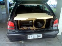
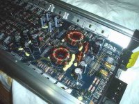
Nordic:
Here is one of the power amplifier people use here, many channels, transistorized or FET output.... DC supply is around plus and minus 35 volts...output impedance goes to 2 ohms...so...200 watts peak is possible...and many channels man!
A switching power supply makes the DC to DC convertion to a higher voltage...it sucks 80 amps from the 13.8 Volts batteries.
Yes!!!...more speakers and more amplifiers are used too...this one is very small compared to others.
The brand is from USA..... i love North America!!!.... and the brand has a perfect name....BOSS
regards,
Carlos
range of power...problems..if appear, will be above your audition levels.
hehe
DX corporation Marketing department is turning crazy with my dear friend Klaas (a nice guy...guaranteed)...he is the Dx amplifier terminator, and this because of some accident that will be discovered soon or latter...i hope the guilty is that scope..or scope probes.
.......................................................................................................
Nordic:
Here is one of the power amplifier people use here, many channels, transistorized or FET output.... DC supply is around plus and minus 35 volts...output impedance goes to 2 ohms...so...200 watts peak is possible...and many channels man!
A switching power supply makes the DC to DC convertion to a higher voltage...it sucks 80 amps from the 13.8 Volts batteries.
Yes!!!...more speakers and more amplifiers are used too...this one is very small compared to others.
The brand is from USA..... i love North America!!!.... and the brand has a perfect name....BOSS
regards,
Carlos
Attachments
- Status
- Not open for further replies.
- Home
- Amplifiers
- Solid State
- Destroyer x Amplifier...Dx amp...my amplifier