I am sorry about the confusion, Carlos.
I just tested at 30 watts, this was done during 15 mins. continuous testing.
But this was not maximum power before clipping.
Today i measured using short bursts (~3 seconds).
This was measured using 2200 uF ps-caps (1000 uF on pcb),
rail-fuses are 2A slow, rail-resistors still in place:
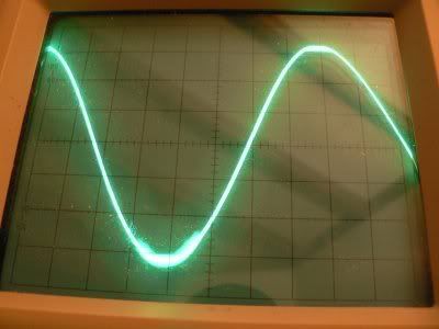
Scope is at 10V/div, test-frequency was 600 Hz.
Dummy-load is 6.75r 40watt.
If i did the math correctly it is clipping at 67 watts.
Best regards,
Klaas
I just tested at 30 watts, this was done during 15 mins. continuous testing.
But this was not maximum power before clipping.
Today i measured using short bursts (~3 seconds).
This was measured using 2200 uF ps-caps (1000 uF on pcb),
rail-fuses are 2A slow, rail-resistors still in place:
Scope is at 10V/div, test-frequency was 600 Hz.
Dummy-load is 6.75r 40watt.
If i did the math correctly it is clipping at 67 watts.
Best regards,
Klaas
Possibly a little instability here Klaas,
This might be cleared by dropping the Zobel Resistor value down to 4.7 ohms non-inductive. If not the value of the Miller connected C.dom at the VAS could be adjusted.
Cheers ...... Graham.
This might be cleared by dropping the Zobel Resistor value down to 4.7 ohms non-inductive. If not the value of the Miller connected C.dom at the VAS could be adjusted.
Cheers ...... Graham.
Graham is rigth...increase the miller capacitor to 33pf, also increase the feedback
one to 22pf and reduce the zobel resistor to 4.7 ohms or even 2,2 ohms till you have this superimposed hi frequency sinal out of the waveform.
Check in advance...increasing the scope sensitivity, with one meter wire in the input...if you have some interference sinal in your surrounds....it can modulate the sinal because can be detected in the base to emitter junction (working as radio frequency diode detector).
This hi frequency level seems to be very big in voltage...have to be removed Klass.
Thank you to test it deeply...go ahead...will be pleasant to see more bugs...and even this way sounding fine.
Your scope signal is showing unstability, as i could see, when the power is around the clipping levels...it may be worst if your input frequency goes high...say, 22 Kilohertz.
I have used TIP41 and TIP42 transistors as drivers, and also a TIP41 unit as voltage amplifiers, a sacrifice made to high frequencies reproduction to avoid those possible unstabilities..that use to appear in many amplifiers.....the perfection over trebles was sacrificed for realibility....also to avoid Miller capacitors, or to load the output with a different Zobel.
Those TIP transistors are not able to oscilate (work) at very high frequencies, they are not good to produce oscilations or to let high frequencies goes ahead into the next stage.
This signal you have Klass, this one you shown us in the scope screen, if measurable, different from noise, try to inform us, please, the main frequency there.
A good idea also, will be to short the rail resistors and fuses...as they can be the guilty...as we have not so big rail condensers in place.
I have checked using simulator, once more,...and nothing unstable there...you see how much we can trust in those things...not too much i think, as a lot of differences will appear in real life, board construction, parts and all stuff together can change result....simulator is some optimized mathematic reality.... not really connected to real life.... a pretty tool that will squeeze (drift, derrapa, escorrega) when driven with the reality grease.
regards,
Carlos
Thanks Graham.
I feel like i'm standing on the shoulders of giants here - meaning you and Carlos.
I'm not very knowledgeable about this kiind of testing, i just build the stuff
This is what i tried after reading your post:
I put another 10r resistor parallel to the existing zobel-resistor - i guess these are wirewound so they are inductive.
This didn't help.
Increased 5.6pF cap to 12pF across VAS-transistor (bd243c), also no improvement.
Tried paralelling a coil//10r resistor at the output, before this i took the output directly from the zobel.
This didn't really help either.
I noticed the behavior on the positive side of the signal is much worse than on the negative side btw.
Should i try increasing the value of the cap further , maybe 22 pF ?
With kind regards,
Edit after reading Carlos' post: I checked the ouput-signal of my pre-amp which is feeding the amplifier (measured at the input of the power-amp) and the signal looks perfecly clean. I will try increasing to 33 pF.
Have to go shop for that, don't have 33pF cap. Luckily the shop is just 15 mins. from my home (carries entire E96-resistor range in stock - yes i know i'm lucky 🙂 )
Klaas
Oh!...this is a promotion to me, to stay at same level as Doctor Graham Maynard!
In the reality, i am not enougth to polish his shoes...he talks with me because he is kind, as i am too much ignorant to have a deep conversation with him.
Interesting...my resources are going to finish with the suggestions i gave in the last post i made.... at same time you were typping i think.
Remove the rail resistances and fuses....put a good wire in that place...and try once more.
The feedback capacitor can be increase a little without too much losses.... the reduction is a problem there, as it is sensitive when going down..and not sensitive when increased.
Do not go up 33 picofarads in the Vas.....because sinusoidal wave form will turn into triangle around 60 Kilohertz using bigger condensers there.
Hummm...maybe the differential feedback transistor one.... a 1000pf from base to emitter.
If your increase of zobel.... the output coil removed or increased...well..those modifications did not worked, so, re-insert the old values once more.
Please, check if you have that signal around your home.... install wire, vertical, as antena...and use the biggest sensitivity you have in your scope (also inform what is this sensitivity) to check if you have this signal inside your home...cell phones, cameras and a lot of home appliances produces some small signal...including economic lamps, those ones that have a transistorized oscilator inside.
Graham....HELP!...if you have an idea...please, go ahead.
regards,
Carlos
Klass...for testing purposes you can install capacitors in parallell
10 plus 10 picofarads will result in 20 picofarads...this may work fine for testing purposes only...not needed that shop visit
because of that capacitor.
Of course i think you already know that...but it is good to remember as you has the intention to go shopping because of that...maybe not only because of that.
regards,
Carlos
Attachments
the positive side of the signal is much worse than on the negative side
Hi Klaas, the positive behavior is clipping, the negative a kind of oscillation...
Good luck with this nice little DX amp.
Loek
Hi Klaas, the positive behavior is clipping, the negative a kind of oscillation...
Good luck with this nice little DX amp.
Loek
Thanks sofar guys 🙂
Loek, the scope-image i've shown was inverted, so the oscillation is on the positive side.
I've tried removing the fuses+ rail-resistors, this seems to have cleaned up the signal to some extent.
Negative side looks clean clipping now (was oscillating also), positive side still shows oscillation.
Maybe i should tidy up the powersupply-wiring, it's kinda crappy right now.
My scope is kinda crappy , it has trouble locking on to hf-signals 🙁
Also everything is not connected to earth (including the scope), it's running off the safety-transformer i mentioned earlier.
Probe unconnected picks up lots of noise at 1 mv/div (maximum sensitivity)
Best regards,
Klaas
hehe...those things are very normal to happens
You will find the way to clean this wave shape..go trying...and tell us also about the sonics..if you perceive something wrong with sonics too.
With lower levels the signal is clear!... am i rigth?... i think so.
regards,
Carlos
You will find the way to clean this wave shape..go trying...and tell us also about the sonics..if you perceive something wrong with sonics too.
With lower levels the signal is clear!... am i rigth?... i think so.
regards,
Carlos
It's good to get some elbow-grease, Carlos, it is a good way to learn things. It makes you try harder and remember better.
I tried increasing cap across VAS-transistor to 24 pF (put another 12 pF in parallel) , no change.
So i guess that road is closed.
The signal is clean until ~ 50 volts pk-pk (approx. 46 watts output)
the differential feedback transistor is the one with its base connected to the feedback-network ? sorry for my stupid questions..
My time is a bit limited the rest of the day (party to attend to 😀 )
But will try some things you mentioned when time permits.
As you always say, Carlos, don't worry, be happy 🙂
Klaas😀
Yes...relax...never mind..be happy..it is just an amplifier...not more than that.
The feedback transistor, is the one you have the feedback capacitor....the one connected with its base into the output line thougth a resistance in parallell with a very needed capacitor.
What is you voltage amplifier transistor number..the one that use that Miller capacitor?
This BD244 is not a good idea as drivers...and if used as voltage
amplifier it may produce problems...voltage is very limited..and you have an big Peak to Peak voltage swing.
Try BD139/140.....or something alike....MJE340 and 350 is a good idea too..well...there are hundreds of possible matches there.
The output units are also strange..they were used, in early past, only for switching supply purposes...a switching transistor...now a days they are appearing as audio amplifiers too...hummmm...dangerous...place 10 pf from colector to emitter..to each one of them for testing purposes only..watch if your signal turns clean..if not..just remove those small capacitors....not needed to be 10 pf...can go from 5 pf to 22 picofarads there without big problems.
regards,
Carlos
Attachments

hummmm...this one is nice, but strange to audio i think
Give a capacitor try on it....intall capacitors on them..the output complementay units.
Yes...they work in audio very well...as you could see..but...they love to oscilate...you had the experience.... an enormous strong transistor and it may gone with that bias experience...maybe oscilated during those adjustments...danger unit i think.
regards,
Carlos
Attachments
not connected to earth
Maybe another thing, is the heatsink grounded?
If not this can act as an antenna and with higher power couples maybe to the input circuit/wire. Also separate input and output/pwr-supply wires.
My 2 eurocents.
Loek
Maybe another thing, is the heatsink grounded?
If not this can act as an antenna and with higher power couples maybe to the input circuit/wire. Also separate input and output/pwr-supply wires.
My 2 eurocents.
Loek
This makes sense...but what is "my 2 Eurocents"
Loek, is this some idiomatic expression that may means:
"This is my contribution"
regards,
Carlos
Loek, is this some idiomatic expression that may means:
"This is my contribution"
regards,
Carlos
Well...as i made the amplifier, of course i am biased.
And i will accept any possibility.
The guilty may be the supply
The guilty may be ground
The guilty may be his Scope
The guilty may be his mains
The guilty may be his neighboor
Or maybe his pants...ahahahah!.
But i will seach for the guilty....never the amplifier....ahahaha!...this is funny!
regards,
Carlos
😀 😀 😀 Carlos, don't get me started about my pants lol, we don't know eachother that well 😀
Well i went shopping for the caps 🙂
what i have tried since is reroute the powersupply-wiring/ input-wiring.The oscillation is still there.
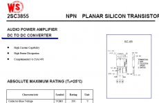
The 2sc3855/2sa1491 devices i use for output are Sankens,
the VAS-transistor (bd243c) is an ST-device...
Drivers are bd243c,bd244c (both ST)
I picked up the Toshiba 2sc5200/2sa1943 yesterday, i hope they are genuine.
Also i have mjl 21193/21194, might be worth a try.
I'm done soldering for today, time to party 🙂
Thanks everybody for being so helpfull sofar.
With kind regards,
Klaas
Well i went shopping for the caps 🙂
what i have tried since is reroute the powersupply-wiring/ input-wiring.The oscillation is still there.
The 2sc3855/2sa1491 devices i use for output are Sankens,
the VAS-transistor (bd243c) is an ST-device...
Drivers are bd243c,bd244c (both ST)
I picked up the Toshiba 2sc5200/2sa1943 yesterday, i hope they are genuine.
Also i have mjl 21193/21194, might be worth a try.
I'm done soldering for today, time to party 🙂
Thanks everybody for being so helpfull sofar.
With kind regards,
Klaas
More close up pictures Klaas...hehe...to inspect more!
If your transistor were fake...a capacitor from base to colector will kill oscilations there...say...those 2SC5200 and counterpart.
There are more possible solutions.
-Jumper over the output coil
-Install a capacitor 102 or even bigger, from base to colector, into the feedback transistor
- Install a series of 100 pf with 100 ohms between input colectors.
- The increase of the Miller capacitor.
- The increase of the input capacitor
- The increase in the feedback capacitor
- Small capacitors into the drivers, from base to colector
_ A try of capacitors, small units from base to ground, into drivers units and output units.
If nothing of that fixed...i will blame your scope!
If not acceptable i will scape to Mars with one way ticket.
regards,
Carlos
Attachments

I was burning my last neuronium trying to find the problem.
And i remember that i have asked to Mr. Greg Erkine, from our forum, to change boards in a better way to install output transistors in horizontal position.
He told that migth have problems there...but i have insisted that probably no problem will happen...a risk i took.
Observe the output coil, it is possible that there's the problem...you can see that distance is not so big from the input and feedback differential transistors.
And there's you will have a lot of voltage and current....so...a lot of power that will mean a lot of magnetic energy surrounding the coil.
observe the board.
regards,
Carlos
Attachments
- Status
- Not open for further replies.
- Home
- Amplifiers
- Solid State
- Destroyer x Amplifier...Dx amp...my amplifier