I was saying "you're welcome" to Nordic, Carlos.
Dutch (my native language) and South-African are closely related.
Cousins so to speak lol
Best regards,
Klaas
Dutch (my native language) and South-African are closely related.
Cousins so to speak lol
Best regards,
Klaas
thanh said:many members who sent email
Can you blame them ?
Some guys get into the hobby to get away from girls.
Many are nerds who start electronics because they're not good at catching girls.
If you show them a pretty picture they remember again that you can hold hands with a soldering iron but you can't kiss it.
Chao (?)

KVholio, thank you by the translation...interesting is to observe as people have
different ideas related the rail protective resistances.
Your decision was a very low value...not to protect i think...in the reality you wanted to measure your stand by current.... i am talking about the 0.47 ohms resistance in parallel with another one....seems to me that are rail protective, as you are using fuses too.
I think you already know...but take care about those fuses...measure if you will have voltage in their extremes when the amplifier was playing loud....it is common they behaving as resistances.
I like the way you have installed the heat sensor diodes... your construction is very good.
I will watch your transistor specifications....very interesting those things...each one of us with our preferences related parts.....this is excelent.
I am curious related your voltage amplifier transistor gain...can you inform me...datasheet will tell me some about them, but real gain is difficult as it variates a lot.
regards,
Carlos
.................................................................................................
Good to have you here Jacco.... some fun, good mood is welcome....but sadly, it seems to me that those Viets guys do not use our forum the way they could.
In my point of view...there's nothing against the them...exactly the opposite.
regards,
Carlos
Attachments

No. I didn't answer their question. I guess that there are some members still look forward my email 😀 😀Can you blame them ?
Some guys get into the hobby to get away from girls.
Many are nerds who start electronics because they're not good at catching girls.
If you show them a pretty picture they remember again that you can hold hands with a soldering iron but you can't kiss it.
Chao (?)
If you can't see below words, please choose UTF-8 encoding for Internet Explorer
Việt Nam
Xin chào: hello, hi
Attachments
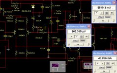
Related to those drivers, i noticed a silly mestake: i mentioned bc243c/bc244c, it should be bd243c/bd244c. silly mestake 
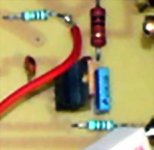
Rail-resistors are 0.47 r// 0.68 r.
They are just for measuring current, fuses are there for protection.
You are right about fuse-resistance Carlos, to make matters worse they are dynamic resistances, resistance is varying with current-draw of the circuit.
At 30w rms they lit up like a christmas-tree .
Mounting the diodes on the aluminium bar was just convenient, given big thermal inertia of the bar and its coupling with op-devices and heatsink i figured it would be okay.
I made this heatsink for universal use, i can mount different types of op-devices without drilling/tapping new holes.
It also provides superior thermal coupling compared to using screws.
I used stainless-steel threads/nuts, cause in my experience threading in aluminium eventually wears out.
A much belated thanks Jacco for pointing me to safety-transformers a long time ago. Got one of those 1.6 kva hernia-inducing military-greenish thingies now , i use it for my 'projects' every time
Best regards,
Klaas
Replacing those fuses and removing the rail protective resistances
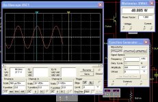
Your clean power will jump to more than 40 watts RMS clean...well, that's what i had here....maybe your fuses and protective resistors (if already there) are reducing the usefull power.
I could have more...near 50...or 48 to be precise, but i have perceived that distortion was already appearing....something that may be around 0.5
Interesting is that my series resistor....related those diodes, was a 33 ohms....when the simulator show 120 to 150 ohms and your circuit used 25 ohms....maybe the diodes used...in the simulator was 1N4148...in my circuits i have used 1N4007.
The voltage amplifier Klass...if you know the gain, please, inform it to me...also the transistor number.
regards,
Carlos
Attachments
Re. good evening Thanh
You can have all the information you need about electronics components in www.digikey.com. If you like to make an order you have to pay for the freight charge which is some $20 per order and tax for Vietnamese authority. you will have your components in 2-3 weeks after the order is accepted. If you purchase in bulk it will be great, the price is reasonable. And the parts are absolutely genuine.
Let me see a 2sc5200 price ranging from $1.98 to $2.48 a piece which is more than than double compared to 28.000 apair and 14.000 a piece. Your trans is half as cheap as the ones from digikey. This is the same story with all the power trans on stock at Electronics Shop in VN. there's some shop sell reliable MJ15023-15024 which are second hand, you can count on them.
Your trans come from HN which in turn taken from China source. The price in HN is 26000-27000 and in HCm city 28000. This is exactly the one I refer to. Its SOA is acceptable but linearity is not. As the result the treble sound of your amp is noisy and the bass will loose due to poor damping factor. But this is the best trans I found in the shop.
The Emitor Resistors I refer to are both in tip41 and 2cs2383 emiters. I use this VAS circuit and the sound is better than ever.
I'm going to help our friends improve their Chinese amps.
If have the genuine parts there's no need to apply sophisticated circuit. Just use the simple circuit from sir Destroyer X. That's enough. The complicated circuit is made only to alleviate poor electronics parts performance.
Have fun!🙂
further notice
you have told about gain and oscillation.
first, gain: the circuit here is a current amplifier. the 2 pair of trans (c2383-a1013;tip41-42) do the work of as a single darlington. I think there nothing to care about gain in here. I chose Tip 41 for it is powerful and can drive big power trans. I will be able to drive A1216-C2922 with this circuit.
second oscillation: I have a problem with them too and burned a lot of power trans. the reasons:
- lack of (02) VAS capacitor (10-150pf)
- ground loop. You need to separate ground for input and output
- noisy power supply for driver stages. A +/- 50 V regulator for the driver stages is recommended. The amp's performance is much better.
You also need a good transition capacitors between Power Amp and preamp for better performance. (MKP, MKII of 1,5-2.2mf which is available in VN market). More luxurious, Wima capacitor with 0.47MF each is desirable.
OP amp:NE5532, TL072 are quite fine in despite of they are faked.
I think that there's two amplifier running at same time and place...we can call the
Viet amplifier as some version of Dx amplifier, for sure they are not so enormous in differences.
I do not bother with this, but i was thinking that people may confuse, as i did, what amplifier is beeing mentioned each time.
I think that Thanh and Phong Vu Tuan amplifier has differences in the supply voltage related the Dx amplifier, and also it is different related output topologie...so...there are some rules that cannot be applied to both of them.
I am writing this only to avoid too much confusion...there are two amplifiers beeing subject here...and some care will be needed not to confuse them.
Thanh, a good and old friend, and also Phong Vu tuan are always welcome in my threads as they are good fanatics alike i am...this is not the problem....i want only to remember folks that there are two amplifiers runing at same time here.
I think, or imagine, that thanh and his friend are talking about their version.
regards,
Carlos

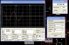

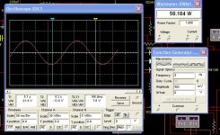
15 hertz losses....observe that the input capacitor was modified to 1 uF
Because Klass had to use an enormous capacitor (in size)...and really not needed so big that way...sorry Klass
I have simulated with 1uf at the input.
This was obtained (simulated) over 4 ohms
regards,
Carlos
Because Klass had to use an enormous capacitor (in size)...and really not needed so big that way...sorry Klass
I have simulated with 1uf at the input.
This was obtained (simulated) over 4 ohms
regards,
Carlos
Attachments
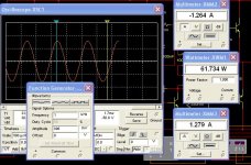
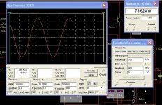
Here you can see the power losses over 4 ohms
Because i have reduced the input capacitor...so...now you have losses there.
But you can see that it is very good even this way.
Power obtained by Mr. Klass was reduced because he had fuse problems and i suppose the voltage amplifier gain not so good.
We will see in near future if Klass amplifier power will change.
Those simulator results makes sense related the real life audition and real life measurements made....but triangle wave started before in frequency..simulator is too much nice in this aspect.
regards,
Carlos
Attachments
- Status
- Not open for further replies.
- Home
- Amplifiers
- Solid State
- Destroyer x Amplifier...Dx amp...my amplifier