trimmer cpacitance trimcap
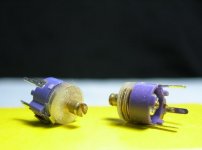
I bought these 2 trim-caps long ago.
Can't even remember what I intended to use this for 😀
If I am not mistaken, they are like 10-50 pF ( violet colouring )
Mounting is 3 pins.
Pin spacing is 5.08 mm ( 2/10 of inch ).
Looking at my attachment image ( sorry for all the dust )
from this you can figure out they are small.
One thing I have learned:
 Do Not use metal screw driver
.. to adjust small value trimmer caps or trimmer inductors.
There are special non-metallic plastic screwdrivers,
we should use.
Or you may find some other thin little plastic piece in your room,
that fits for adjusting.
lineup
I bought these 2 trim-caps long ago.
Can't even remember what I intended to use this for 😀
If I am not mistaken, they are like 10-50 pF ( violet colouring )
Mounting is 3 pins.
Pin spacing is 5.08 mm ( 2/10 of inch ).
Looking at my attachment image (
sorry for all the dust )from this you can figure out they are small.
One thing I have learned:
Do Not use metal screw driver .. to adjust small value trimmer caps or trimmer inductors.
There are special non-metallic plastic screwdrivers,
we should use.
Or you may find some other thin little plastic piece in your room,
that fits for adjusting.
lineup
Attachments
I was a Radio Amateur from 1965 to 1991 and those ones
Use to produce some drift...you adjust and they go changing value while the mechanic system goes into place.
So....for instance...you adjust to 10 picofarads and they drift to high or lower level...and 11, 12, 13 and they can stop in 15 picofarads.... very unprecise those ones.
the problem is to adjust and them, and then to remove them to measure out of the circuit.
After removal, the previously adjusted capacitance value will already have some drift.... so...your adjusted value,that one made when the trimmer was soldered into your amplifier... that one will be the reference to search for a fixed unit, with this same value, and this one will be installed in the feedback line, as the best possible adjusted value (by ears)....well..it will be wrong because of the capacitance drift, consequence of bad mechanics.
Normally they go from 10 percent to maximum capacity.for instance, 5 to 50....or 10 to 100 pf.
Your can be different..of course they can be constructed using different ranges and rules.
regards,
Carlos
Maybe Graham has, already tested, a small circuit having Varicap diodes.
This will turn things better, as i will have more precision and no mechanical drift.
I can try some...but the problem is that i will have to make it, using try and error....better if Graham has already done circuit for this purpose.
It is boering to calculate all those things....having some circuit dear Graham, i will have to re-calculate only mine own varicap range to voltage and the series with the output series capacitor... as circuit may see those two capacitors, the varicap and the output one, beeing a system with a resistance .
The resistance, to avoid that the amplifier circuit load the whole thing, can be placed in another position to avoid too much calculations.
regards,
Carlos
Attachments
Hi Carlos,
Yes I think that a useful arrangement.
15pF might be a little too low for you to be able to home in on the optimum value. Maybe something like 50 to 75pF would be better, or the oscillator section of a sub-min AM portable oscillator section with the trimmers removed.
The reason I say this is that once you exceed the optimum value the effect upon reproduction is much smaller than when the value is below optimum. Thus you need to be able to swing way too far, so to speak, in order to be able to home in on what is actually best. This cannot be done when the trimmer has a value similar to capacitance needed.
Also it is not right to physically hold any component connected to the base of the NFB sensing transistor in the differential pair, nor have any wires (varicap) connected to it.
Cheers ........ Graham.
Correct Graham...you are rigth....the wiring will have an uncontrolled capacitance
that will create more problems than solutions.
The old and good padder or some small air gap variable condenser will be used...i will pick some hammarlund in my friend's house.
Thanks...it is good to have you here.
regards,
Carlos
that will create more problems than solutions.
The old and good padder or some small air gap variable condenser will be used...i will pick some hammarlund in my friend's house.
Thanks...it is good to have you here.
regards,
Carlos
re. Amp sound
I have made am amp with such design with power trans: 2sc5200; 2sa1943; 2sa1930 and its 2Sc. Power rails: +/- 50V The amp just work fine, no smoke, no extreme heat. This amp is designed at 80W but only good at 20 w and the treble is not clear enough. At higher power output, the bass is quite loose which is so bad.
I have some changes in the driver, adjust quiescent current and the result appear to be OK. All the trans in the power stage are bias with 70ma quiescent current. And a compound pair with current limiter is added before the power trans.
I will be happy to see your schematic Phong, including your modifications
Thank you to inform us about your unit.
I have perceived that bass loose you told, when i was testing emitter resistances....and adjusting gain too...now it is fine.
Mine unit, working with 38 Volts is producing absolute clear sound till 40 watts... in my imagination 0.1 % of distortion there...and increasing till 0.5% around 50 watts.
Graham, can you please inform us those numbers you have simulated?
Pictures, listening impressions, reviews, schematics will be welcome Phong... in special the old schematic where you had only 20 watts of real clear sound....very good your experience and informations....goooooood!
Please, go ahead.
regards,
Carlos
Hi Carlos,
Simulating the last circuit you posted with the grey background, gives 0.12% @ 40W 1kHz into 8 ohms load.
If the two 100 ohm emitter resistors at the differential input pair are shorted out this becomes 0.10% @ 40W 10kHz into 8R.
Both the above with a single output pair.
With parallel connected output pairs having separate 4R7 base resistors the 0.10% figure holds for 80W 10kHz into 4 ohms.
The distortion is predominantly odd harmonic, but falling with order.
The square waves are clean too.
Simulators are not 'real life' but the performance is most definitely useful.
Hi PhongVuTuan,
At 50V rails I feel you would be wiser to double up on output devices for 8 ohms, and quadruple for 4 ohms, with additional 4.7 base resistors as necessary.
My choice for driver transistors would be 2SA1837 and 2SC4793, with the latter being used for the VAS.
I wonder which device you are using for your VAS.
Also when rails increase above about 35-40V there is a need to increase the value of a Miller connected VAS C.dom.
Carlos shows 5pF. Maybe increase it to 22pF @ +/-50V.
Cheers ........ Graham.
Well... Phong did not return with some more informs.
For sure his amplifier is not the beautifull Dx amplifiers, as his unit is behaving very bad.
Your simulations, Graham, are matching what i am measuring when listening, as i have an AC voltimeter connected at the output all time long...so...i am watching the output all time long.
Also i have tones recorded from 5 hertz to 10 Kilohertz that i use to check....it is clear when the amplifier starts to clip....not needed an Scope to perceive that scandallous awfull sonics of the clipping.
I have made the testing using FM inter stations noise.... 18 pf seems to good Graham...... increasing it the difference is small....but decreasing it from those 18pf you can perceive clearly differences.
Phong told something about a current limiter somewhere...well..if this is in the supply we already know the reason why his amplifier is behaving so bad.....with current limiter the amplifier will be, for sure, limited in power.
Hey Phong...you sent a bomb in my amplifier, as you told about another one...almost the same...behaving very bad.....some folks may believe DX amplifier will be bad too....hummmmm, not real thing.
I hope you find time to show us your amplifier.
I imagine you are very busy, and not that "accidentall bomber" your post suggest.
regards,
Carlos
Thanks by those informs Graham.
My Tina shows me a very small distortion...wonderfull graphics!...so pretty ones that i do not trust them....as
amplifiers, the good ones, normally distorts, you can see
real data from many op amps and chip power amps, all them
showing 0.5 percent somewhere.
Also my Multisim 2001 tells me the amplifier as perfect....and
it is not perfect real life....the perfect ones, or the less bad ones, sounds awfull.
One that i can remember was Blamefest.... i made it perfectly,
was adjusted and i was terrified with the results....it received
a double barreled shot....i did not made some movie of that...
my error.... i would be happy to see it exploding once more.
Well..... i feel myself as some retired related amplifier construction, i am satisfied with the experiences i have made in
this life...maybe in the next life i will produce "Zonic Positronic Signal Enlargers".... Dx amplifier, or any bootstrapped well adjusted amplifier, is enougth to show me a lot of things i
had doubts...now i have sure and i will only follow other guy's
constructions...electronics now, for my life, is alike a movie to be watched once
more...as i already know the end of the movie...the bandit, the
heroe and everything that gonna happens i already know.
No dear Graham, i did not noticed differences with the output coil removed.... i was imagining that coil not working always, using all speakers....at least, with mine ones...nothing happened..... but i can believe, because make sense, the need to use, and also the advantage to remove it in some cases.
Sound of bells turns less rich without those 100 ohms emitter resistors that you can see in the differential, as you told, they increase distortion a little ...and that distortion increase turns more rich the bell sound....i could perceive it as better, but i have to tell you that i prefer that distortion that turns the bell sound more dense.....more perfect amplifier without regenerative or degenerative resistors (i do not know the name...maybe degenerative)...yes....better amplifier to meterings without them.
Well....i perceive as the end of the electronics chapter of my life..as i can remember during the seventies a cheap amplifier having TIP3 and TIP4 transistors... the output of a bootstrapped amplifier.... with not more than 10 watts that turn me crazy by its sonics... and it turn even better when i included more condensers in the supply and more diodes in parallell (they were working hot).
Since that satisfaction moment i started the survey to find something better...that one was cheap and simple, and people were starting with some "Strombolic"....from Stromboli...from young children stories.... those confused schematics filled with CCS, mirrors, double, tripple supplies, giant condensers, Fets in the input, advanced off set adjustments, incredible temperature compensators...well....my diode was there..touching the heatsink with some small dot of thermal grease...and relays... SCRs and swithing things, sensors, distortion Leds, special metering circuits, automatic fan blowers.... and i started to search for something better.
I have found the best in the Aksa amplifiers, and my DX is a distant cousin of Aksa amplifiers...the old Nirvana...the Aksa 55.
Exactly the same circuit i perceived as good 37 years ago...that cheap one i found in the seventies....i made the long run...i have assembled more than 4 thousand amplifiers..and i am telling you that those bootstrapped ones are the best possible circuit to give you good sonics....not Scope measurements.... those others have to be bougth by Scope.... some distortion analiser have to go to shopping and buy those modern ones!
regards,
Carlos
Attachments
In the end of a long thread by Carlos
All things must end.
At what sounds like the end of a good Carlos topic
it can be nice to look back and have a look at it all.
I think my first opinion in my first post about DX-Amp
(see a bit of it above here )
is one that will still holds as close to what I really think.
Looking forward to next travel, next journey ....
... in the next interesting to read thread by Carlos
Not everything is audio - some of us has got a life, too!
Thanks my friend
your
lineup - so far away .. but so close to you and your family in his mind
🙂
lineup said:
destroyer X said:
Everything that did not made difference
...... perceived by ears...removed!
What you describe, is what many of us like the most,
AKSA & Nelson & Lineup & SEWA Father Mad_K,
... now we add to this 😎 Hall Of Fame Group😎
... one more member:
Carlos 'The Very Productive Ingenious amplificador Destroyer'
***********************************************
Method: KISS
FullName: Keep It Simple, Simple!
HowTo: Do not add stuff that you can do without, and still keep a very good operation!
----------
When great audio designers, like me for example,
refer to A Piece of Wire
we simply refer to
-----> The Ultimate Ideal and best Component EVEEEEER <-----
lineup
All things must end.
At what sounds like the end of a good Carlos topic
it can be nice to look back and have a look at it all.
I think my first opinion in my first post about DX-Amp
(see a bit of it above here )
is one that will still holds as close to what I really think.
Looking forward to next travel, next journey ....
... in the next interesting to read thread by Carlos
Not everything is audio - some of us has got a life, too!
Thanks my friend
your
lineup - so far away .. but so close to you and your family in his mind
🙂
Hi Carlos.
So you can hear a difference related to the differential emitter resistors.
These resistors are not only a part of the signal path, but the NFB path also, and for this reason I prefer to NOT use them. Personally I dislike a 'bright' SS sound, yet some NFB designs can also seem 'ice cold', but then wouldn't it be boring if we all thought the same!
When I hear a component or circuit induced difference in sound, I then investigate to find which is more faithful to amplifier input, because I would prefer that the recording engineers' intended reproduction performance came through unadulterated so that I could subsequently adjust to choice if necessary for personal preference afterwards.
Thus I would not accept an amplifier modifying the waveform, and I would look in case there might be a deficit elsewhere for some characteristic which those resitors might be compensating for. The best way I find to compare input to output is via headphones.
So there are many here who shop as you suggest - though in the real world the majority become ears on legs when they enter a hi-fi emporium.
hehe...that's rigth!
100 percent agreement on that.
Roger on that!
regards,
Carlos
.....................................................
Thank you Lineup, by your kind words.
Carlos
100 percent agreement on that.
Roger on that!
regards,
Carlos
.....................................................
Thank you Lineup, by your kind words.
Carlos
Re: hehe...that's rigth!
🙂
thanks
kind words and due credits
are just too little of
not only in diyaudio.com
😉
destroyer X said:
Thank you Lineup, by your kind words.
Carlos
🙂
thanks
kind words and due credits
are just too little of
not only in diyaudio.com
😉
Enjoy a guaranteed amplifier, put some Romance in your life
and listen at Dx Sonics....feel the low distortions that made meters happy and float inside the dream to listen into one
of the most "romantic" amplifiers already made.
A genuine cousin of magnificent Aksa*
A piece of jewellery.... a rare sounding machine.
Now next to you... you have just to move.
regards,
Carlos
* Registered Trademark of Aspen Amplifiers Products, the finest
wide world amplifiers.
......................................................................................................
Dx Corporation, in the name of their Marketing Department, inform customers and friends that will not accept provocations anymore....annoying guys will be send to ignore if insist to
unstabilize a nice thread....ahahahahaha!
Attachments
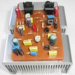
Dx amplifiers, a great small amplifier.
This is some art work done...not a real circuit...but a real board with some real parts over...values are not the correct ones.
A Model only...thing made to show only.
I am just kidding...Dx is not a corporation...nor a factory...i am just a diy as you are...having passion related my "son"..this amplifier.
Not more than that...simple this way.
3 Friends already listening to it...i am already satisfied with that.
regards,
Carlos
Attachments

Re. Amp modification
First I want to say sorry for not sign in so a long time. It's our suck internet which did not response for a week. I have a ton of emails now.
Now don't be too upset about me. I just like to submit a question. why my amp sound so bad. I did the best with my amp with real big power supply caps: 20000 per rail. Voltage regulator for the Amp driver, servo bias for nulling DC, good OP for preamp. . . . But the result is not acceptable. I have a good amp but like to build my own amp. I love amp with good damping factor, clear treble. I have a modification here with the power stage. The trans I use is not good enough, but the result is recognizable. Thanks for further advice.
Attachments
This arrangement, the way you have connected the output is different from mine.
Why not to try mine standard way for a while...for testing purposes only.
Small modifications...some wire jumpers and ready to go!
I suppose you have tried to remove the suckout condenser..this one in parallel with the resistance....if not, try it without and listen to it.
regards,
Carlos
Why not to try mine standard way for a while...for testing purposes only.
Small modifications...some wire jumpers and ready to go!
I suppose you have tried to remove the suckout condenser..this one in parallel with the resistance....if not, try it without and listen to it.
regards,
Carlos
re. output stage
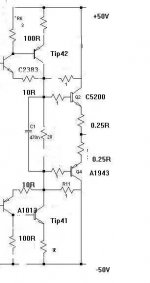
Yeah, you know I like your design in a way that it's very simple and require very few components. Most amp circuits sold in our Electronics shop are using your design. At first I made exactly yours, then that didn't bring good result. I think it was the transistor quality is not linear enough. I read an article from some Elliot Electronic page. They tell me some thing not OK about the linearity of Darlington. I switched to this new schema and I think I have solved the linearity problem. My point is creating a class A - Amp to drive the power transistor. The quiescent of the Tip41-Tip42, I put at 75-100ma far exceeding the base current of the power trans. The tip41-42 must have a good heat sink. With this design I don't have to care much about trans quality. Now I'm going to find some bad trans to work with my amp to see the difference.
Prior to this, I have a slight change to take 4 pair of 2sc2383-2sa1013 to make a parallel network to drive C5200-A1943. It worked quite OK.
I made my Amp with a main placing all the power supplies: +/-50V; regulated +/-20V, +/- 55V, +/- 5.6V for Power Stage, gain stages, preamp and input selector. The Power Stage of the amp is also on the main board. I have a Plug-in Drive card, containing high gain stages. I have made several cards using some design other than yours: symasym. (I use only one 2.2MF capacitor in the audio path which is MKP); I have a VI limiter that cut down at 4A wich is a little bit high. And still the sound quality is not improved. From this experience I know that, the poor quality of my amp is caused by Hfe linearity of the output trans.
Furthermore, I have a from input Ground to Power ground to avoid hum.
Now I'm quite happy about the amp with no hum, better damping factor and linearity. Why don't you have a try, and tell me some thing about it. 😎 Have fun
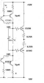
By the way, I forget 2 additional resistors that do nothing in the scheme, here is the scheme
Yeah, you know I like your design in a way that it's very simple and require very few components. Most amp circuits sold in our Electronics shop are using your design. At first I made exactly yours, then that didn't bring good result. I think it was the transistor quality is not linear enough. I read an article from some Elliot Electronic page. They tell me some thing not OK about the linearity of Darlington. I switched to this new schema and I think I have solved the linearity problem. My point is creating a class A - Amp to drive the power transistor. The quiescent of the Tip41-Tip42, I put at 75-100ma far exceeding the base current of the power trans. The tip41-42 must have a good heat sink. With this design I don't have to care much about trans quality. Now I'm going to find some bad trans to work with my amp to see the difference.
Prior to this, I have a slight change to take 4 pair of 2sc2383-2sa1013 to make a parallel network to drive C5200-A1943. It worked quite OK.
I made my Amp with a main placing all the power supplies: +/-50V; regulated +/-20V, +/- 55V, +/- 5.6V for Power Stage, gain stages, preamp and input selector. The Power Stage of the amp is also on the main board. I have a Plug-in Drive card, containing high gain stages. I have made several cards using some design other than yours: symasym. (I use only one 2.2MF capacitor in the audio path which is MKP); I have a VI limiter that cut down at 4A wich is a little bit high. And still the sound quality is not improved. From this experience I know that, the poor quality of my amp is caused by Hfe linearity of the output trans.
Furthermore, I have a from input Ground to Power ground to avoid hum.
Now I'm quite happy about the amp with no hum, better damping factor and linearity. Why don't you have a try, and tell me some thing about it. 😎 Have fun
By the way, I forget 2 additional resistors that do nothing in the scheme, here is the scheme
Attachments
- Status
- Not open for further replies.
- Home
- Amplifiers
- Solid State
- Destroyer x Amplifier...Dx amp...my amplifier