The resistor is very non critical. 1k, 10k, anything in between. All will work.
Both TL072 and NE5532 are good for audio. The NE5532 has better output capability so would be a better choice for the filter, the FET based TL072 has better imunity to rf and would be good for the input stages. Mixing opamp types is no problem, use them according to their strengths. 20% tolerance on caps for a fliter like this isn't an issue in practice. Its not as if you are making a high Q notch filter or anything like that.
Just one thought, and it depends how far you have gone into constructing all this, would be to make the first two stages inverting and to use a proper "virtual earth" mixer for summing the channels.
last night i brought all this to the breadboard.
i'll try to upload a circuit diagram today.
OK. That would be good. Up to now we concentrated on getting all the stages electrically correct. You need to be sure the response is what you want, particularly the two series connected filters for the low pass output.
Does LTSpice not run in Linux (with wine) ? I've never used Linux but I think it can be made to run.
Does LTSpice not run in Linux (with wine) ? I've never used Linux but I think it can be made to run.
wine has been a bad solution for me.
i experienced instability which i thought i got rid of when switching vom windows to linux.
i use use eagle cad now.
it is not too easy to handle, but it is ok.
i experienced instability which i thought i got rid of when switching vom windows to linux.
i use use eagle cad now.
it is not too easy to handle, but it is ok.
You are right, wine does not work well with everything.
But it is very good with LTspice which I use.
About Eaglecad, it has a native linux version.
But it is very good with LTspice which I use.
About Eaglecad, it has a native linux version.
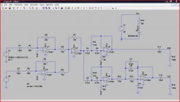
i worked a little bit on the diagram.
it should show what i did last night.
i don't know if i will run a test tonight, because i will get home very late.
i'm not sure about the polarity of the elko.
but i tried to share my thoughts about the power supply.
Vcc, Vz and Vo are the used potentials in the circuit.
any chances this might work?
That looks OK. The cap is fine. Take your audio ground from your V0 line.
(I might redraw your circuit using inverting configuration. And are you sure a HP filter followed by a LP filter is what you want ?)
(I might redraw your circuit using inverting configuration. And are you sure a HP filter followed by a LP filter is what you want ?)
That looks OK. The cap is fine. Take your audio ground from your V0 line.
does that mean that i should leave it like it is?
(english language is difficult to me)
(I might redraw your circuit using inverting configuration.
inverting configuration?
because the adder inverts the signal once and so it has to be done once more in an output stage?
And are you sure a HP filter followed by a LP filter is what you want ?)
high out:
everything above 150Hz.
low out:
between 40Hz and 150Hz.
Last edited:
Yes, leave it as it is 🙂
Inverting... your new diagram isn't correct. Look at the opamp inputs of the adder. If we change the adder to "inverting" which is better for performance, then we need to change the input stages to inverting too.
Inverting... your new diagram isn't correct. Look at the opamp inputs of the adder. If we change the adder to "inverting" which is better for performance, then we need to change the input stages to inverting too.
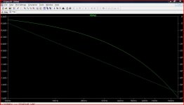
I've just put it into LTspice (to draw and run). You have a problem I think with the filter response.
sounds not good.
what does this mean?
what can i do?
Last edited:
I made a basic error in the simulation above ... trying to do to many things at once 🙂 Let me run it again.
i don´t get this preamp thing out of my head although i have tons of work to do.
i´m thinking about variable crossover frequencies.
when i look at the low-pass i might change the resistors to a 50k linear stereo pot in series with a 5.6k resistor and that paralleled to a 60k resistor.
might give an variable xo between about 40hz and 220 hz.
i´m thinking about variable crossover frequencies.
when i look at the low-pass i might change the resistors to a 50k linear stereo pot in series with a 5.6k resistor and that paralleled to a 60k resistor.
might give an variable xo between about 40hz and 220 hz.
Variable gets complex.
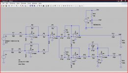
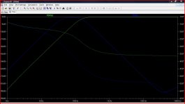
Here is the response and full circuit of your original concept. High pass in green and low pass in blue. Note all the grounds and all the Vref points. Also note that it is now inverting at the input and adder. Note also the opamp - and + inputs.
Here is the response and full circuit of your original concept. High pass in green and low pass in blue. Note all the grounds and all the Vref points. Also note that it is now inverting at the input and adder. Note also the opamp - and + inputs.
Attachments
I have w8 installed on my desktop at home.
You changed the values of the input caps and resistors.
Can i stick my values (because i have those components in stock)?
You added capacities and resistors on the output.
Can i change the caps into 1uF?
You changed the values of the input caps and resistors.
Can i stick my values (because i have those components in stock)?
You added capacities and resistors on the output.
Can i change the caps into 1uF?
- Status
- Not open for further replies.
- Home
- Source & Line
- Analog Line Level
- Designing a noob-preamp (single supply)