For such low power circuitry you could include a low value resistor in series with the supply as protection. I've no idea what could be happening with the other IC's but to melt them takes some doing As mentioned, if the supplies on pin 4 and 8 are correct you can connect the other pins anywhere and everywhere within the limits of those supplies and the IC won't even blink.
it works!!!
thank you very much, mooly!!!
Just seen that (over the page 🙂) Excellent.
Hi,
i thought maybe the error occured, because i connected the power amp to same supply.
from as far what i understand there should be no problem in driving the preamp and the amp paralled to the same supply.
this the idea behind designing the power supply of the preamp like it is.
i don't want to waste more opamps if possible.
maybe someone can confirm that it should work?
or maybe i should attache a safety-diode?
Remind me 🙂 draw your PSU (there have been a zillion posts since this one).
There should be no problem running the preamp off any supply as long as it is done correctly. For such low current opamps I would use a simple resistor and zener shunt supply. It does everything you need and is very low noise and impedance too.
There should be no problem running the preamp off any supply as long as it is done correctly. For such low current opamps I would use a simple resistor and zener shunt supply. It does everything you need and is very low noise and impedance too.
hi,
of course it works with the amplifier paralleled to the psu.
i'm still amazed, what i can get out of 11€ tpa3116 board in pbtl mode driven by sla batteries.
the newly build 12" sub is too much for my neighbours with this setup.
i have the preamp soldered to a prototyping board in the meantime.
it sounds a bit better now.
a crossover frequency of 90hz seems to be fitting the setup with the big fr-horns.
but my impression is that the sub needs sharper cutoff than 12db.
i think about rebuilding the whole thing with 4rd order sallen-key filters.
do i have to change anything about the input/output buffers?
mooly, maybe you can point towards a website, where it is described how to calculate the buffer stages?
Sounds like you are having fun.
I can't see any reason to change the input buffers as they simply provide a defined input impedance and give you the option to set any gain that may be needed. Is that what you mean... calculating values for the buffers ?
I can't see any reason to change the input buffers as they simply provide a defined input impedance and give you the option to set any gain that may be needed. Is that what you mean... calculating values for the buffers ?
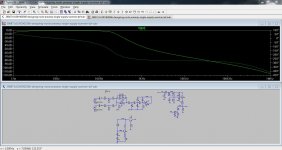
I have done a simple summer-lpf in ltspice, give it a try.
Neatly done 🙂 I'm not sure if our friend is up to speed on simulation (says me 😀) but if not here is a plot etc of it. I shorted your LED out.
Attachments
Yes, not too sure of skill level, but I thought to through it out there for anyone to try it out.
I referenced my old National Audio Application handbook, a TI app note on single supply op-amp applications
-Single-Supply Op-Amp Circuit Collection-
doc #: sloa058
Oop's I guess you did not have the blue led model, it was merged in from Bob Cordell's models.
I have a variable supply class d amp and want a constant led brightness if the supply v is changed.
It is as simple as ltspice can be 🙂 I am at least slightly productive with the tool.
Damn, I wish I had ltspice back in college.
TI app note on single supply op-amp applications
-Single-Supply Op-Amp Circuit Collection-
doc #: sloa058
i´ve looked through that some weeks ago.
although i didn´t understand everything, it was quite inspiring for me to start this project.
I have done a simple summer-lpf in ltspice, give it a try.
i see a kind of input buffer, a summer, a 3rd order mfb filter, something that seems to make "virtual mass" and something ... i don´t have any idea what it is.
is that meant as a better alternative to cascade 2nd order s-k-filters?
is the method of the psu for the opamps better than the one use or is it just required for the mfb lpf?
or is it inspiring in a way i don´t get atm?
my question about the input buffers relates to a post mooly made.
he said something like:
'you cannot just throw in anything as input buffers, you have to calculate them.'
A simple summer and a 3rd order butterworth filter set at 125Hz.
The supply is a capacitor mutiplier
The led is run at a constant current
I guess Mooly is referring to the gains, you have calculate and/or sim to get what you want. The filter(s) have insertion losses. You want to balance the gain through each filter section or have a gain control for each filter section.
is the mfb filter superior to sallen-key in any way?
i like s-k for being simple to build.
even my noob-eyes see which resistors must be changed for which effect.
AND i only have to change resistors for different xo-frequencies.
the gains can be controlled by the choice of resistors in the buffer and summer section.
is it possible that some combinations of resistors can cause problems?
i remember some combinations didn´t work.
then i changed one resistor for a different gain and it suddenly worked (something like gain of 7.5 didn´t work, but 4.5 did, my multimeter said all resistors were ok).
what about the input and output caps?
how do i know their values?
is it possible i already have a problem with phase delay?
maybe because of the way i soldered it?
i remembered how it sounded a bit weird at first.
then i changed + for - at the speakers.
sounds better and i already forgot i did that.
arrrggg....
too many questions for one post.
...and i have so many more of them.
is the mfb filter superior to sallen-key in any way?
i like s-k for being simple to build.
even my noob-eyes see which resistors must be changed for which effect.
AND i only have to change resistors for different xo-frequencies.
I'm no expert on filter design but know that choosing the correct type of filter for the job in hand is important, S & K, Butterworth, Chebyshev... they all have unique characteristics such as in band phase response, ripple in the pass band etc.
Without looking up as go I couldn't advise you on that.
the gains can be controlled by the choice of resistors in the buffer and summer section.
is it possible that some combinations of resistors can cause problems?
i remember some combinations didn´t work.
then i changed one resistor for a different gain and it suddenly worked (something like gain of 7.5 didn´t work, but 4.5 did, my multimeter said all resistors were ok).
Ask away. You would have to post diagrams showing your circuit but it sounds as though something construction wise might have gone astray on that one. Gain of 1, gain of 100, there should be no real problems.
Yes, some combinations are not ideal but generally that refers to very high or low resistor and feedback network values.
what about the input and output caps?
how do i know their values?
What about them 😀 Values are easily calculated once you define the other parameters such as source impedance, wanted LF response, your wanted input impedance and so on.
is it possible i already have a problem with phase delay?
maybe because of the way i soldered it?
i remembered how it sounded a bit weird at first.
then i changed + for - at the speakers.
sounds better and i already forgot i did that.
arrrggg....
too many questions for one post.
...and i have so many more of them.
I doubt construction and soldering itself gives any errors at the frequencies involved here. Construction errors, yes, but not layout and soldering at these frequencies.
As a low pass the MFB has many advantages over both the unity gain S&K and the variable gain S&K (equal value component S&K).
D.Self explains why the MFB is not quite as good for high pass duty. Just as well I bought his filters book.
MFB, has gain that is independant of frequency and Q.
frequency and Q are set independantly.
is inverting and thus becomes a summing stage, simply by adding extra input resistors.
D.Self explains why the MFB is not quite as good for high pass duty. Just as well I bought his filters book.
MFB, has gain that is independant of frequency and Q.
frequency and Q are set independantly.
is inverting and thus becomes a summing stage, simply by adding extra input resistors.
As a low pass the MFB has many advantages over both the unity gain S&K and the variable gain S&K (equal value component S&K).
D.Self explains why the MFB is not quite as good for high pass duty. Just as well I bought his filters book.
MFB, has gain that is independant of frequency and Q.
frequency and Q are set independantly.
is inverting and thus becomes a summing stage, simply by adding extra input resistors.
thanks, this post was good input to me.
now i have an idea why some diagrams for active xo show different types of filters in the same circuit.
i think my next version of the xo wil have that, too.
What about them 😀 Values are easily calculated once you define the other parameters such as source impedance, wanted LF response, your wanted input impedance and so on.
is there a formula, a system of equations or a differential equation?
where can i look that up?
adding volume control is better
a) closer to the input
b) closer to the output
of the preamp.
i´ve seen some designs with inverting amplifiers on the outputs used as gain control.
why not do that at the input buffers?
edit:
stupid question!
i want the high- and low-out with different volumes.
i´m sitting on my *** the 4th day in a row.
i´ll go out for a run now.
tonight i will get my hands on ltspice and try to draw a new diagram.
i´ll be back to ask for some help, when don´t get the simulation running.
Last edited:
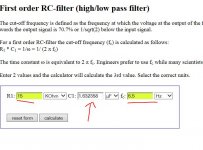
Input and output caps are calculated as follows...
Decide your input impedance. This is the "input" resistor for the common opamp configurations. The one from + input to ground for the typical non inverting amp or buffer and the one in series with the - input for the inverting configuration. Decide your wanted LF point.
So lets say 15k input resistance and an LF point of 6.5Hz and lets see what we get.
(the LF point is when the signal is 0.707 of the input voltage... the -3db point)
The formula for all these is 1/(2pi F*C)
Its even easier with an on line calculator 😀 Try this, scroll down to the filters section, pick your units and enter two of the three variables,
calculators for electronic circuit design
so, all the input cap does is cutting out very low frequencies?
could a simplified answer be something like:
'just calculate a rc-filter that cuts out everything below ~10hz.'
?
that would be easy.
but:
why do i need that?
do the opamps not like those frequencies or is it about power consumption?
does a bandpass make sense to also cut out the very highest frequencies?
- Status
- Not open for further replies.
- Home
- Source & Line
- Analog Line Level
- Designing a noob-preamp (single supply)