I've no quick answer to your filter problem, you would need to start from the begininning and analyse the response of each section and make sure it conforms to your own spec for what you want.
i´m at the damn university again and the pc doesn´t allow me to install ltspice.
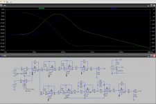
i took a "measurement" from each section.
the very last amplifier in the high-signal way corrected a similar effect at the high-out.
i remember that the crazyness in the low-path started with lpf-stages.
i will post pictures tonight.
Feeding two identical power amps from one feed should be OK... although some will say its not ideal. I can't really see a problem though.
that´s great news.
every single component isn´t that expensive, but it adds up and i need to save every cent i can for buying food and coffee ...... and new breaks for my bicycle.

the green line is taken after the last lpf section.
the blue line is from the low-out.
something strange happens around u4.
mooly, with the simple pot at the output i see the problem that i will not be able to mute the signal completely.
Can you post the .asc of your circuit?
C9 & C10 should be connected to Vref instead of ground, as should all of the resistors signal grounds (R27 & R 28) except before the input DC blocking capacitor and after the output dc blocking capacitor.
jer 🙂
C9 & C10 should be connected to Vref instead of ground, as should all of the resistors signal grounds (R27 & R 28) except before the input DC blocking capacitor and after the output dc blocking capacitor.
jer 🙂
Last edited:
C9 & C10 should be connected to Vref instead of ground.
that would not work.
mooly, with the simple pot at the output i see the problem that i will not be able to mute the signal completely.
I don't quite follow you on that. A good pot will attenuate down to zero as the wiper comes into contact with the ground terminal.
I don't quite follow you on that. A good pot will attenuate down to zero as the wiper comes into contact with the ground terminal.
you're right of course.
i'm still thinking of a pot just as an adjustable resistor between 0 ohm and x ohm.
Last edited:
Yes.....It does work and is what caused the error in your simulation. 😉
jer 🙂
that's great news.
as it was it worked with the first version, mooly had it in his suggested circuit and a ti-doc with examples for single supply applications showed it with the cap to ground.
Any node that would normally be connected to ground using a bipolar supply should be connected to Vref using a single ended supply.
You can also tie the Vref with the input and output signals ground points providing your circuits V- supply is isolated from the next devices V- that is a common ground.
Else connect the input and output signals as assumed in your schematic if the above condition is not met.
As the DC is blocked by the input and output capacitors and will only pass AC through to the next amplifying stage.
Remember that this is the same thing as a Power Amplifier that has an Output Capacitor and run off of a Single ended supply. 😉
The more opamp's that you use be sure that your Vref source has a low enough impedance to acommadate all of the extra opamp stages for +/- swings on the virtual ground (Vref).
The input current of the LT1057 is very very low at 4-50pa but should you use some other type of opamp (Bipolar types) this could easily be much higher and exceed the rating of your Zener diode setup and have an imbalance of the positive swing impedance vs the negative swing impedance in your virtual ground and this can/will induce common mode distortions.
Select your zener's dropping resistor accordingly.
This is not anything to be worried about now, But it is something that you should keep in mind if you get to designing a circuit such as a large mixer or something that has lots of, or even hundreds, of opamp's in it. 🙂
Also the zener diode setup cost much more than just using two resistors for your Vref. 😉
FWIW
jer 🙂
Last edited:
gerald, i`m glad you entered this thread.
looks like you have a lot of useful knowledge for my noob-agenda.
as you didn`t follow from the beginning and i still owe some info about the use of the whole project, here it comes:
the preamp will (shall) be used as an active crossover and volume control to feed two (maybe more later) tpa3116 boards.
one of them is driving two fullrange horns.
the other one runs in pbtl-mode and drives a subwoofer.
the whole thing is running on sla-batteries.
as the setup is meant to be also used for outdoor purposes, high power efficiency is crucial.
i`m going to use tl072 for the buffer stages and 5532 for the filters.
any suggestions are warmly welcome.
especially when it comes to cost, efficiency and size/simplicity optimizations.
Okay, Cool !! 🙂
I had suspected that you may be using other opamp types and I did look up the NE5532 as a worst case scenario.
The input bias current of just one stage of the NE5532 is in the order of .0002ma to .0008ma this is 40,000 times higher than that of the LT1057 that you are using in your simulation.
Even though you are using say 8 or 9 of them but lets say that you are using 10 of them total per channel and double that for stereo.
Using the NE5532's you would have a total input bias current of 2ma to 8ma for one channel and this already exceeds the current that your Zener Vref can supply as set by the 10k resistor.
As 9V/10k=.9ma !!
Since you want to use battery power then the NE5532's are not a good choice as they will eat 8ma to 16ma of current for each stage alone!!
The LT's are great and TI also has some opamp's that you should consider as well that will give good performance and not be so expensive such as the TLC or some of the OPA series depending on what kind of packaging you desire.
The LME series is the best for SQ but I am not sure if any of them are suited for portable power.
Op Amp Circuits | Op Amp IC | Amplifier & Linear Solutions | TI.com
Low Noise Amp * - Products - TI.com
The TL07x's are hard to beat in this mannor for cost.
I had made a fuzz box octavider that used a single TL074 and CD4013 and I would get something like 2 or 3 months (maybe a little longer) of use out of it without ever turning it off using just two 9V battery's.
Being that it was a high gain device it did draw a good amount of current when i used it, But it did last much much longer than when I used the good ole' LM324 in it.
I just realized that you used a LT1056 in your simulation and I was thinking the LT1057....Oooops!!
No Biggy, but the LT1056 does have 6 times the input bias current at 30pa then the LT1057's 5pa.
TI's TLC series would be great for this, But, they are only rated for 16Vmax as I had mentioned before.
They does have a bit better performance than the TL0xx counter parts but they do have a lower supply rating.
I have fried a few of these in the past not realizing this, a few times, and it is the main reason I never used them.
But they did have good sound quality.
http://www.ti.com/lit/ds/slos583/slos583.pdf
I re-opamp a small Fostex 454 with TL072's and it gave my Mackie 32-8 mixer a good run for the money and was just as clean and quiet.
At the time (1994) Mackie was designing with the new wonder chip the JRC4560.
The Fostex was very very quiet and transparent with the TL072's compared to the stock version when it was loaded with JRC4558's and 4556's.
I tried using the NE5532's in the sweepable filter stages but it just turned some of them in to variable sweep oscillator's so I kept them in the straight signal paths.
I never did investigate why this was.
But I am sure this had to do with the impedance of the components in the filter circuit as they may have been to high for the NE5532 to stay stable.
I have read of others with similar issues trying to modify their crossovers using them.
And there have been a few discussions about this.
Your resistors of 12K are low enough as I have seen them used for such circuits as filters using the NE5532, so you shouldn't have this issue but they will eat some supply current.
A while back there was a DIYer that wanted to build a 5 band EQ to use with is personal player and the issue of opamp's for battery power came up but I forget what he choose to work with.
FWIW
jer 🙂
P.S. Maybe something like the TL07x EP would be good at only 1.6ma of current drain but will still have the SQ performance and voltage rating of a standard TL07x.
This would increase your battery performance of nearly 8 to 10 times than you would get using the NE5532's.
However they are only come in a SOIC package, But they are not hard to work with and would give you a small footprint PCB.
😉
http://www.ti.com/lit/ds/symlink/tl072-ep.pdf
Last edited:
thanks, gerald, that was good info.
i think i´m going to stick with the tl072 as i already have them.
can you please draw me an example of the power supply you mentioned.
i thought that using a voltage divider would be worst case for efficiency.
i think i´m going to stick with the tl072 as i already have them.
can you please draw me an example of the power supply you mentioned.
i thought that using a voltage divider would be worst case for efficiency.
Yes, I will do that it is very simple.
Here is the other version of opamp That I couldn't remember the number, The TLE207x series it is basically the same as the TLC parts but has a higher voltage rating like the TL07x's,
Operational Amplifier (Op Amp) - Precision Amplifier - TLE2074 - TI.com
The TL072's are very fine components even to this day and I think you will be happy with them.
But if you were to get any more I would consider the EP version as it has even better spec's and performance at a lower power consumption level.
jer 🙂
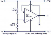
Here is a page that explains the technique I am talking about,
Single Supply Op Amp Design
You can use a high value of resistors to divide your powersupply in half to create your Vref such as 100K to 1 meg each as shown in the schematic.
This will allow a very very minimal amount of extra drain current from the supply.
Since your circuit uses an odd number of opamp's (as drawn) you will have one left over that you can configure the extra one as a unity gain amplifier to feed your virtual ground system with a low impedance Source/sink Vref.
You can/may have to add a small decoupling capacitor in parallel with the bottom resistor to help with noise.
But this circuit will only draw as much current as needed be by the demand of the virtual grounded components with the exception of whatever the Idle current of the opamp stage is at about 1.4ma.
Else you would be have to be drawing an extra 5ma or so if not more all of the time using just resistors for or Vref bias circuit.
As two 1K's in series would make a constant 9ma of current draw were the Opamp will supply that only if it is needed.
And will be only for short intervals on very high peaks of signal swing when needed.
This also solves the common mode issue I described earlier as the battery voltage starts to droop. 😉
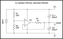
The second picture shows a 741 but any opamp you are using will work the same.
You don't need the resistor unless the opamp shows some sort of instability.
jer 🙂
P.S.Here are some more examples,
https://www.google.com/search?q=vir...yLYv2qwHD7YH4DA&ved=0CH0QsAQ&biw=1280&bih=865
Single Supply Op Amp Design
You can use a high value of resistors to divide your powersupply in half to create your Vref such as 100K to 1 meg each as shown in the schematic.
This will allow a very very minimal amount of extra drain current from the supply.
Since your circuit uses an odd number of opamp's (as drawn) you will have one left over that you can configure the extra one as a unity gain amplifier to feed your virtual ground system with a low impedance Source/sink Vref.
You can/may have to add a small decoupling capacitor in parallel with the bottom resistor to help with noise.
But this circuit will only draw as much current as needed be by the demand of the virtual grounded components with the exception of whatever the Idle current of the opamp stage is at about 1.4ma.
Else you would be have to be drawing an extra 5ma or so if not more all of the time using just resistors for or Vref bias circuit.
As two 1K's in series would make a constant 9ma of current draw were the Opamp will supply that only if it is needed.
And will be only for short intervals on very high peaks of signal swing when needed.
This also solves the common mode issue I described earlier as the battery voltage starts to droop. 😉
The second picture shows a 741 but any opamp you are using will work the same.
You don't need the resistor unless the opamp shows some sort of instability.
jer 🙂
P.S.Here are some more examples,
https://www.google.com/search?q=vir...yLYv2qwHD7YH4DA&ved=0CH0QsAQ&biw=1280&bih=865
Attachments
Last edited:
Since your circuit uses an odd number of opamp's (as drawn) you will have one left over that you can configure the extra one as a unity gain amplifier to feed your virtual ground system with a low impedance Source/sink Vref.
i don´t understand every bit of this.
-odd number of opamps
-> i have also a few tl071 in stock
-extra one as a unity gain amplifier to feed your virtual ground system with a low impedance Source/sink Vref
-> you mean the circuit you have posted?
In the circuit you have posted for one channel, it uses 9 opamp stages this leaves one opamp stage left over assuming you are using a dual opamps.
Else for stereo you can use just a single TL071 for your virtual ground driver if you wish.
jer 🙂
Else for stereo you can use just a single TL071 for your virtual ground driver if you wish.
jer 🙂
i hope mooly is not getting jealous while i´m flirting with you.
Ahhhh,ha,ha,ha,ha,ha,ha it is possible !!!! He,he,he,he 😉
Sorry, Mooly!!! 🙂
jer 🙂
i hope mooly is not getting jealous while i´m flirting with you.
Not at all 🙂
There are many ways to look at a problem and everyone has their own ideas.
- Status
- Not open for further replies.
- Home
- Source & Line
- Analog Line Level
- Designing a noob-preamp (single supply)