I thing this is +/-1% resistor, where ,red=2, second red=2 ,black=0,black=0 zeros.You add 22R in positive rail it's ok.
Regards
So this is a 220R resistor.
4band 220r would read: red, red, brn, brn = 2, 2, 1, 1% = 220r+-1%
5band 220r would read: red, red, blk, blk, brn = 2, 2, 0, 0, 1% = 220- +-1%
But both of those could be read back to front, since red is +-2%
5band 220r would read: red, red, blk, blk, brn = 2, 2, 0, 0, 1% = 220- +-1%
But both of those could be read back to front, since red is +-2%
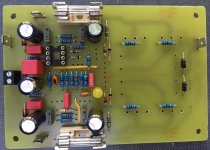
It's exactly what I have built (only Zobel is 4R7 + 100n due to lack of components).
Thanks to Mile. The amplifier sounds very nice.
regards Olaf
Thanks to Mile. The amplifier sounds very nice.
regards Olaf
I hope Mr. Mile will share this F400 version.
This F400 is over 15 years old and I must redraw pcb and schematic with some upgrades.
Regards
If it's just the demand for more pairs without changing the circuit, it should not be so hard.
regards Olaf
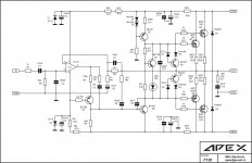
Use F110 circuit with 4 output pairs it is F400.
Regards
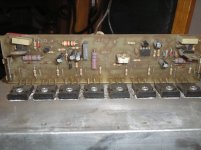
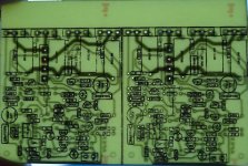
Hi, here are a few photos of my second trial with the F120. I could not get it stable running.. A few times he was working, then again not, I have found no reason for it.
Does not matter. Because I no longer had patience to look for, I have a new attempt and started a new layout and a new prototype. Let's see. I will report.
🙂
regards Olaf
Does not matter. Because I no longer had patience to look for, I have a new attempt and started a new layout and a new prototype. Let's see. I will report.
🙂
regards Olaf
Attachments

Hi, here are a few photos of my second trial with the F120. I could not get it stable running.. A few times he was working, then again not, I have found no reason for it.
Does not matter. Because I no longer had patience to look for, I have a new attempt and started a new layout and a new prototype. Let's see. I will report.
🙂
regards Olaf
I suggest F110 for new prototype.
Regards
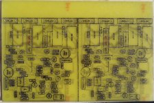
To late 🙂, some more components installed.I suggest F110 for new prototype.
Regards
regards Olaf
Attachments
Hello
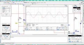
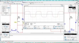
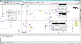
I was simulating the F100 and I notice that after I simulate with 20K the sine wave does not stay smooth and has some sort of anomaly "not to be alarm" so I spend a few hours checking and it come that R22 4.7k I changed to 600R so now even if you go more than 20KHz it will continue to keep the output nice and clean, I mean this is my diy thinking I might be wrong, what you guys think ? 🙂
well I just re-drawing the F100 and add a trim pot and also a illustration of the original R22 4.7k to be placed there or trim pot 1K to do fine adjustment 🙂 also a re-drawing of the supply too please if some one see a mistake let me know I will leave the Sprint Layout 6 file here please only for diy to enjoy yourself guys 😀 I wandering if mister Terry already made it 🙄 ?
Regards
Juan
Attachments
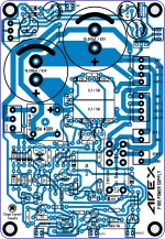
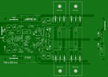
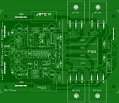
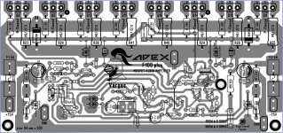
question, I was just making a larger version of the F100 and I was wandering if a coil can be add it to the circuit ? this layout is not test it yet just in case 🙂 I already simulated and respond really well, I think 😉 , I have to completed and check for errors here is the layout now "not tested"
one note the R34 can be adjusted to 1.5K and that will give about 45mA so reading one of the 0.22 5W resistors is about 10mV to be on the save area 🙂
I know is not like BJT but not to be abuse them jejejejejeje 😛 been mosfet
Regards
Juan
one note the R34 can be adjusted to 1.5K and that will give about 45mA so reading one of the 0.22 5W resistors is about 10mV to be on the save area 🙂
I know is not like BJT but not to be abuse them jejejejejeje 😛 been mosfet
Regards
Juan
Attachments
Last edited:
Nice work, go to post #35.question, I was just making a larger version of the F100 and I was wandering if a coil can be add it to the circuit ? this layout is not test it yet just in case 🙂 I already simulated and respond really well, I think 😉 , I have to completed and check for errors here is the layout now "not tested"
one note the R34 can be adjusted to 1.5K and that will give about 45mA so reading one of the 0.22 5W resistors is about 10mV to be on the save area 🙂
I know is not like BJT but not to be abuse them jejejejejeje 😛 been mosfet
Regards
Juan
Regards
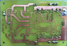
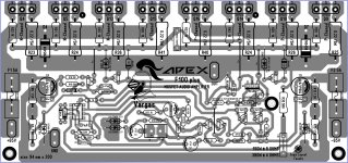
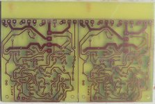
I find this old pcb, same schematics with 5 pairs of mosfets, bias adjustment and protect on board, but files was lost.
oh man is that the file got lost that is so sad 🙁 it will be a great re-drawing 🙂
I will check the F100 with 5 pairs on simulation to see how it responds
Regards
Juan
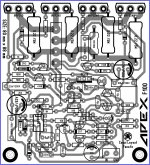
F100 ready to populate. Fun stuff tomorrow. 😀
Hey you did it great ! man let me know how is the tune sound 🙂
I was checking the larger version I'm making I had I missing cap I just add it today 😀
Regards
Juan
Attachments
- Home
- Amplifiers
- Solid State
- DC Servo MOSFET Amplifier