I have a few questions to ask
1. What would be the recommended ac voltage and transformer VA rating?
2. In place of the mr diodes, can I use mbr20200ct?
3. Are all the resistors in the h-step 1/4watt?
4. Can I use 1watt versions of all the zener diodes?
5. Instead of the ifrp240/9240 combination, can I use irf540/9540 and if so how many?
6. Wat are the voltage ratings for all the bipolar capacitors ?
Sorry for so many questions I want to get this right the first time.
Last edited:
On this PCB exept PSU is short-circuit and DC protect, clip indicator...
Dear Mr. Mile,
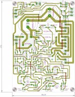
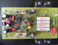
here is my eagle version of your PSU+Protect+Clip PCB. I found a few discrepancies in the schematic, but I laid the PCB as per your PCB layout. pl inform if there are any errors.
regards
prasi
Attachments
Hi,
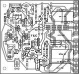
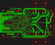
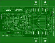
I've never tried an amplifier from this thread. So here is the first draft of a F120.
It would be nice if someone could look at it.
I hope, next weekend I will find time for etching PCB.
regards Olaf
I've never tried an amplifier from this thread. So here is the first draft of a F120.
It would be nice if someone could look at it.
I hope, next weekend I will find time for etching PCB.
regards Olaf
Attachments
Hi,
I've never tried an amplifier from this thread. So here is the first draft of a F120.
It would be nice if someone could look at it.
I hope, next weekend I will find time for etching PCB.
regards Olaf
Nice pcb,
Regards
Dear Mr. Mile,
here is my eagle version of your PSU+Protect+Clip PCB. I found a few discrepancies in the schematic, but I laid the PCB as per your PCB layout. pl inform if there are any errors.
regards
prasi
Mr.mile any comments on the layout of PSU? I am getting the psu circuit screen printed to try on for the kelvin amp stereo.
Reg prasi
Mr.mile any comments on the layout of PSU? I am getting the psu circuit screen printed to try on for the kelvin amp stereo.
Reg prasi
It's ok, you just redraw my pcb.
Regards
It's ok, you just redraw my pcb.
Regards
Yes. I redrew your PCB. I am yet to reach a level where I can prepare my own layouts based on your schematic. . thanks for the confirmation. One other help. I did not like the sound of lm3886. My cheap commercial solid state amp makes much better sound. I have posted this query in lm3886 thread. Tell me whether kelvin amp can be used as a full range amp and can it produce audiophile quality sound? I am interested to know the specs of kelvin amp.if you have. Like thd. Imd . bandwidth etc.
Sorry for mistakes as I am typing from mobile.
Reg
Prasi
Hi,
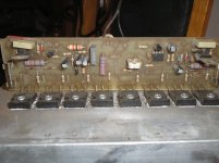
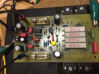
I have assembled the F120. The first test shows a lot of trouble
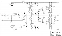
Quiescent current is 160mA but the output has oscillations at about 20 kHz and + -40Vpp. Supply voltage is + - 52V DC. Zobel (4R7 + 100n) is really warm and R18 (22R) is very hot. A signal at the input (0.5V 1kHz sine) can not be seen at the output.
So tomorrow I will go and check everything again and make some measurements.
regards Olaf
I have assembled the F120. The first test shows a lot of trouble
Quiescent current is 160mA but the output has oscillations at about 20 kHz and + -40Vpp. Supply voltage is + - 52V DC. Zobel (4R7 + 100n) is really warm and R18 (22R) is very hot. A signal at the input (0.5V 1kHz sine) can not be seen at the output.
So tomorrow I will go and check everything again and make some measurements.
regards Olaf
Attachments
Hi,
I have assembled the F120. The first test shows a lot of trouble
Quiescent current is 160mA but the output has oscillations at about 20 kHz and + -40Vpp. Supply voltage is + - 52V DC. Zobel (4R7 + 100n) is really warm and R18 (22R) is very hot. A signal at the input (0.5V 1kHz sine) can not be seen at the output.
So tomorrow I will go and check everything again and make some measurements.
regards Olaf
Input gnd and power gnd is not separate on your pcb...
Hi Mile,
yes, unfortunately you're right 🙂. I will correct that. Probably is this not the only error...
Then I'll try again.
Thanks and Greetings
Olaf
yes, unfortunately you're right 🙂. I will correct that. Probably is this not the only error...
Then I'll try again.
Thanks and Greetings
Olaf
Hi Mile,
yes, unfortunately you're right 🙂. I will correct that. Probably is this not the only error...
Then I'll try again.
Thanks and Greetings
Olaf
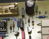
R11 is 220R not 22R...
Hi,
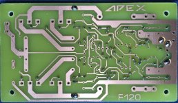
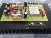
😀😀😀 now the amp is singing 😀😀😀
I corrected the input GND and changed all components in the oscillating negative supply and the opamp.
The sound is very strong and clear, but I tested only on old speakers.
It runs on + -52V, all is cool, quiescent current is only 8mA (?), offset is 1 mV.
Unfortunately my oscilloscope is broken, so I have no other pictures.
I will build the second channel with the corrected layout as soon as I find time 🙂
regards Olaf
Attachments
Last edited:
R11 is 220R. Seems to be ok.
You add 22R in positive rail it's ok.
Regards
- Home
- Amplifiers
- Solid State
- DC Servo MOSFET Amplifier