I do not have any transistors lying around, I need to purchase them for the project. So which output transistors should I get? The standard pairs from Onsemi or the Sankens you are using?
Do You see anything wrong with this board?
1pcs Luxury Power Amplifier Board AUDIO Imitation DarTZeel NHB 108 Power Amplifier Circuit Board|Amplifier| - AliExpress
It has the DC servo, Standard NHB 108 design - but three output pairs.
I was thinking of buying just the board and get components separately. On the other hand, this seller claims they use matched Original Onsemi transistors and that the board is designed for AC voltages up to +-45V.
So maybe I can get this readybuilt board, after all, and just modify/change/add a few components according to your schematic? Will three pairs of output transistors be enough?
FYI: I have (3 in a package deal) 500W 42-0-42 VAC toroidal transformers, 2X10.000uF 80Vx6 rectifier/power boards, fairly large heatsinks and a "power delay soft start temperature protection board", already.
What would you do if you were starting from scratch with the board and had no components (or pcb) lying around?
You obviously do not think the DC servo makes the amplifier sound bad?
As output pairs I used Sanken MT200s 2SC3264/2SA1295 that are obsolete and no more available; you could use the couple MJL3281A-MJL1302A and the couple NJL3281D-NJL1302D, for thermal tracking purpose, as drivers, sharing the same other couples heat sink. At least 4 output pairs, while I consider 6 to be the optimal number; let’s have a low damping factor and not go lower than LJM L20!
Because of Douglas Self explained reasons, you must use 0.1Ohm emitter resistors and a 2.3uH (14awg wire, not thinner) coil paralleled with a 10Ohm 5W resistor before speakers.
The board you linked has 3 output pairs. Provided they are the same transistors as MJL3281A-MJL1302A, I can say that, with respect to one only pair board, they will work under better SOA condition but, if they didn’t reconfigure the two CCS, nothing changes respect to the one pair board. The original CCS supplies around 115 mA, you can use as many pairs as you want, they are driven with nothing more than 115mA. And they miss the Deletraz’s goal to eliminate the Re, because here they must use it. But, for a modding purpose, it should be a good choice even if bulky. An empty board! I do not trust anymore any transistor coming from China.
The original Onsemi transistors work up to 250 and 260V so why do they declare 2x45Vac=126Vcc only? SOA reason? Maybe. Fake stuff reason? Maybe too. My WHA-216 is tested up to 156Vcc with no problem, my power supply doesn’t go over.
I bought two rectifying boards with same capacitors as yours. They all swelled at +/-70V. I solved the problem using more reliable and credible Cornell Dubilier 6.8mF 100V capacitors. Do not use those crappy fakes.
About the mid-point servo: take a look to my #1278 post, there is the schema I modified; with that mod no more bad effect on sound should occur.
About speaker protection: in your picture you show only one; in order to build a dual mono project you must use two of them, the two grounds must remain separated. So buy another and use the two relays in each merged in parallel for each channel. Use a ground decoupler similar to the one I posted at #1288.
I bought a couple of populated board and I blew them while trying a Vbe multiplier, so I reused all capacitors on those boards but the electrolytic and ceramic ones. In a short time I will replace input Wima capacitors (that are not so terrible) with polypropylene ones, but I need time I don’t have. As resistors I used all 1/2W ones in place of those tiny 0,00mW originals. It is better to replace the two 36Ohm resistors with 2W ones.
Do not replace the diodes I added or bias will be not the same.
Bias: the lower the better. Do not increase the bias in order to get some Watts in A class, it is an illusion (read D.Self), this is a B class project, the only thing you will get, pushing it towards A class, is a radiator. A variac is highly recommended for initial power-up.
Thumb up for the transformers if they are good quality stuff; you will get about 140W with a lot lower impedance than original NHB-108 one.
Have attention to the heat produced by MJE15032/MJE5033 transistors, they dissipate around 35W (something less @118Vcc) a channel, while output pairs, at a human listening volume, would run warm if they were on a different heat sink.
After reading so much Self, why don't you build one of his perfect sounding amps and be done with it? 😀
Thank you so much marigno for taking your time and knowledge for this detailed reply!As output pairs I used Sanken MT200s ...."
I will start by measuring the capacitance of the electrolytic capacitors with a little M328 Multi-Purpose Transistor/ESR Tester I received yesterday and then put them under power for a few days to see what happens. I will get -+59VDC, hopefully they can handle that voltage. They are returnable within 30 days and I received them this monday. Also I guess I can use the boards and replace the capacitors, like you did, should they swell.
I will order one more soft start power circuit and the amplifier pcbs and go through your posts before ordering missing components from local suppliers.
The power transformers are from a British company called Canterbury Windings, model TM322A. I bought the lot from a British guy on eBay back in february as a package. At the time I thought I made a great deal.
Only later did I learn about the difference between regular and Audio grade power transformers. So it is what it is. Not shure how it will affect the sound quality and the mechanical noise level.
I do not have a Variac and do not know anyone that does. I was hoping the Soft Start circuits would do the job of protecting the electrolytic capacitors (and amplifiers) from the inrushing current.
Last edited:
Hattori, you should buy another speaker protection and no one more soft start. You need a variac, I wouldn't trust to apply full voltage to any circuit while experimenting, especially a mod told by someone else. Don't worry too much about the transformers: you have then you must use. Unless evidence they are too bad.
I have a strong dislike for any feedback. I accept the local on-stage one, don't like to cross-stage one, and always avoid the cross-all-stages one. I built two (bi-amp) tube main amplifiers, based on the cross-coupled inverter, using only local on-stage feedback. The bass frequencies are a little "long" but the result is a very clear and charming sound. With solid-state, you cannot avoid using cross-stage feedback but you can put the final stage outside the loop, which is the NHB108.After reading so much Self, why don't you build one of his perfect sounding amps and be done with it? 😀
So I picked only some suggestions from Self, the good ones in my opinion. Even if I'm working also to the LJM L20 both v9.2 and V10 boards. I have both the schematics and will trash the V10, where LJM removed all the good and will use the v9.2 with a buffer applied to the VAS; I have no other choice to replace the boards in a 1 unit cabinet with a 100W design. So this is a full Self's design, will see the result.
I was only pulling your leg about Self of course. 🙂
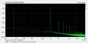
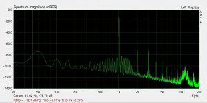
Talking of tube amps, here is a distortion comparison: 5W into 4ohm. Left is the original Dartzeel schematic, right is a pp 2A3 amp with a transformer phase splitter.
Talking of tube amps, here is a distortion comparison: 5W into 4ohm. Left is the original Dartzeel schematic, right is a pp 2A3 amp with a transformer phase splitter.
Attachments
I learned you can only measure the distortion in tube amps by your ears. Ugly graphics, worse on PP, even worse with pentodes. Always lovely sound. Mine are PP of EL34 on Acrosound and EL84 on Trusound, both ultra-linear. I left them in Rome, too far from me to compare with the modded NHB-108. I love them all. Ogni scarrafone è bello a mamma sua (Italian for "any ugly cockroach is beautiful to his mother")
Marigno, I did not buy speaker protection yet. I have a "2000W Soft Start Temperature protection":Hattori, you should buy another speaker protection and no one more soft start. You need a variac, .
220V Class A Amplifier Power Delay Soft Start Temperature Protection Board 6008728722383 | eBay
I thought this "softstarts" the inrushing current through the NTC resistors?
Is this what you mean with a Variac:
VARIAC Variable Transformers
Marigno, I did not buy speaker protection yet. I have a "2000W Soft Start Temperature protection":Hattori, you should buy another speaker protection and no one more soft start. You need a variac, .
220V Class A Amplifier Power Delay Soft Start Temperature Protection Board 6008728722383 | eBay
I thought this "softstarts" the inrushing current through the NTC resistors?
The two relays start supplying full power to the transformers after 5 seconds after power has trickled through 4x6A NTC resistors.
Is this what you mean with a Variac:
VARIAC Variable Transformers
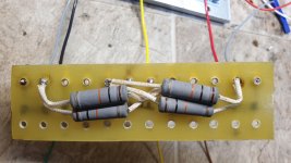
Hattori, you're right, the relays on your board are the same as the ones on a speakers protection I used for another amp. That is a soft start. On my soft start I changed the NTC with an halogen 300W bulb (see the picture), the inrush current is very high, perhaps too high for the tiny NTC with two 625VA toroidal transformers with primaries paralleled. So you have to buy two speaker protections boards. Choose the 30A ones and, on each, use the two relays paralleled for each channel. I used a couple of 4 ways 10A Chinese relay (paralleling the 4 ways) getting confused on the brand: "ONROM" instead of "OMRON" wich is the original brand; the relay is good enough except for the ugly internal wiring that I had to substitute with a true wire. You will need a 15Vac small transformer.
That is a variac. It is the best thing you can use in order to gradually power up any experimental circuitry (not suitable for switching ones). It is expensive but it is worth, if an error is present in your circuitry, you can intercept and fix it; the NHB-108 starts living at about 4-5 Volts, if it doesn't work, it means an error is present and no damage occurs. You can find on eBay the 220/230V ones, I got a Chinese 20A 110V for $90 and works good enough for the purpose.
The original NHB-108 survives a reverse polarity full voltage but do not try.
Attachments

What is the "smallest" Variac I could do with?
220V 4A or 8A? I guess I could test one channel a time, right?
I have found a Chinese brand shipping from Barcelona = no VAT/import duties and reasonable shipping charges:
Metered Variac - Variable AC Output Transformer 8 Amp 0-250V (TDGC2-2KVA) | eBay
METERED VARIAC VARIABLE AC Output Transformer 4 Amp 0-250v (tdgc 2-1kva) | eBay
The ONROM relays are a blast 🙂
Mine are SONGLE which I think is an original Chinese brand 🙂
Last edited:
The cost of the two is about the same, I would choose the 8A one, they are not that excellent quality so let's compensate this with an higher power. Even if the smaller should be good. Your choice. It is not necessary to test, while under variac, the full power of the amp for a long time. Once you reach the voltage you intend to supply the amp with, and everything checks ok, no heath, no smoke, no lights, all is done. Connect a preamplifier and listen to the music. Be sure that, at full voltage, all transistors will work always under SOA condition by design. Or, better, connect the preamplifier with music before powering on, so, while increasing the voltage with the variac, if you can hear the music, be sure it's working. If you can't, after reaching 8V, something is wrong. Yes, you have to test one channel a time. First you try one channel with the untouched original circuit. I think if you are going to build the WHA-216, you will need some pictures showing how to organize the new added components. Let me know.
Hello, how are you doing with your card from Kathern Music?
PCB is great quality but now have no time for building, after holidays I had a lot of work to do.I look forward to starting working on it.
I also just received PCB versions 2.0 which are also great quality.
My plan is to make version 1 first.
Have you solved simply turning the servo circuit on and off. If so, how did you do it?View attachment 860226
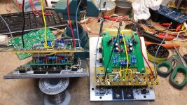
Amplifiers and servoes. Capacitors is underneath the Aluplate. 1000 w transformer 2 x 40 vac.
Is it worth making this amplifier considering the sound quality that is obtained Finally what is the overall sound in the end?No I have not bought this boards. I have heard the only negative a DC servo does is softer bass. When there is no feedback its soft already I think.
Sure will. It will be a while, I guess.Let me know.
Many thanks for all advice!
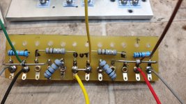
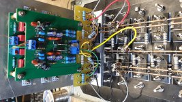
Hattori, these are the pics of how you can organize the added components on a small board. The two 0.1Ohm resistors you see, have the purpose only to test the assembly with one only pair of output transistors you should have on a small heat sink, just to test because you do not want to risk a whole string! Once tested, when you connect the board to the real string of output pairs placed on the big heat sink, the two 0.1Ohm resistors will remain unused, you can remove them, I didn't, you never know. Grey cables are the bases, black is the PNP collector, RED is the NPN collector. One yellow is the common point of all emitter 0.1Ohm resistors. The other yellow goes to the servo to bring the output to be sensed. I replaced the two 200KOhms resistors you see in the picture with 1.2MOhms, as you see in the schema.
Attachments
- Home
- Amplifiers
- Solid State
- Dartzeel amp schematic - build this?