Capacitor test
Thanks!
I am waiting for a schematic diagram of the Kathern Music NHB 108 card w integrated servo and three pairs of power transistor before ordering.
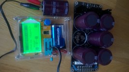
I just tested one of the six capacitors on one of my two power boards:
ESP=0.21Ohm, Vloss=1.3% Capacitance 9120uF.
The capacitance reading I understand but are ESR and Vloss acceptable?
Thanks!
I am waiting for a schematic diagram of the Kathern Music NHB 108 card w integrated servo and three pairs of power transistor before ordering.
I just tested one of the six capacitors on one of my two power boards:
ESP=0.21Ohm, Vloss=1.3% Capacitance 9120uF.
The capacitance reading I understand but are ESR and Vloss acceptable?
Attachments
When buying a PCB, I asked them for a schematic diagram but they did not want to send it to me. They said that it was a trade secret and that they would not give such information.
Thanks!
I am waiting for a schematic diagram of the Kathern Music NHB 108 card w integrated servo and three pairs of power transistor before ordering.
I just tested one of the six capacitors on one of my two power boards:
ESP=0.21Ohm, Vloss=1.3% Capacitance 9120uF.
The capacitance reading I understand but are ESR and Vloss acceptable?
ESR of 0.21 ohm for a PSU cap seems high ( not ideal). You want something in the 0.04-.08 range or lower
Ok.
How will the ESR reading affect the sound/what is the significance of a (lower) ESR reading?
How will the ESR reading affect the sound/what is the significance of a (lower) ESR reading?
When buying a PCB, I asked them for a schematic diagram but they did not want to send it to me. They said that it was a trade secret and that they would not give such information.
Would you mind taking a photo of the back of the card so I can see the traces for the three pairs of power transistors?
(Just trying to figure out if it can be modified according to marignos schematic)
Do not increase the bias in order to get some Watts in A class, it is an illusion (read D.Self), this is a B class project, the only thing you will get, pushing it towards A class, is a radiator.
You have believed a lot of BS from those Self books. No wonder he hates audiophiles and good sound with a passion 😀
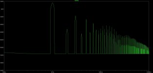
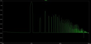
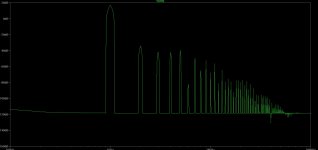
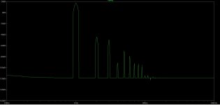
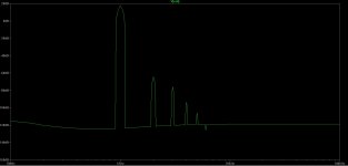
Yet, simulating the 108 circuit shows that increasing the bias leads to a reliable reduction in distortion and especially the high harmonics.
Obviously multiple output pairs will be essential and possibly a reduction in supply voltage. So, probably 3 output pairs and +/-25v supply would be great if one wants to experiment with a lower power class A Dartzeel.
The original seems to have the outputs idling at 220mA, so here is a comparison from left to right of the distortion spectrum @15W/4ohms for bias set@ 80mA, 130mA, 220mA, 770mA, 3.2A
Attachments
-
 Dartz 108 simulated distortion 15W 4ohm 82mA.JPG104.4 KB · Views: 361
 -
 Dartz 108 simulated distortion 15W 4ohm 133mA.JPG101.6 KB · Views: 333
 -
 Dartz 108 simulated distortion 15W 4ohm 225mA.JPG86.3 KB · Views: 327
 -
 Dartz 108 simulated distortion 15W 4ohm 770mA.JPG72.9 KB · Views: 324
 -
 Dartz 108 simulated distortion 15W 4ohm 3.2A.JPG69.1 KB · Views: 127
You have believed a lot of BS from those Self books. No wonder he hates audiophiles and good sound with a passion
You never cease to be amazed by how mesmerizing purely simulation-based theories can be.
You have believed a lot of BS from those Self books. No wonder he hates audiophiles and good sound with a passion 😀
Yet, simulating the 108 circuit shows that increasing the bias leads to a reliable reduction in distortion and especially the high harmonics.
Obviously multiple output pairs will be essential and possibly a reduction in supply voltage. So, probably 3 output pairs and +/-25v supply would be great if one wants to experiment with a lower power class A Dartzeel.
The original seems to have the outputs idling at 220mA, so here is a comparison from left to right of the distortion spectrum @15W/4ohms for bias set@ 80mA, 130mA, 220mA, 770mA, 3.2A
I'm trying to buy another pair of empty pcb that I will fill with better quality components. Also, I have to place the thermal tracking elsewhere because now it senses always the heath produced by the board (small transistors) that is hot, and the output pairs are only warm. Now, working in B class, any automatic bias control would never go under the actual bias. But in the future I will see. However @ 3A it shows the good distortion but it is crazy, I would need far bigger heathsinks. Since it is not my intention going lower than 200W, 3.2A+3.2A @ 140V are 900W in heath. Good during winter, cannot listen at music during summer, or power up freezing air conditioning adding some more KW.
Since it is not my intention going lower than 200W, 3.2A+3.2A @ 140V are 900W in heath.
No, this is not really an option if you need 200W. I lived for a long time with an amp which dissipated 600W idling and it wasn't much fun in summer, spring or autumn.
Btw, i don't quite understand your non-switching concept. Could you explain it a bit?
Is it worth making this amplifier considering the sound quality that is obtained Finally what is the overall sound in the end?
I have a lot of amplifiers. Until now I think Dartzeel is a lousy amp. But I will be back next week maybe with another wiew. Transformers will arrive this week. 2 transformers - one for each channel.
Thanks!
I am waiting for a schematic diagram of the Kathern Music NHB 108 card w integrated servo and three pairs of power transistor before ordering.
I just tested one of the six capacitors on one of my two power boards:
ESP=0.21Ohm, Vloss=1.3% Capacitance 9120uF.
The capacitance reading I understand but are ESR and Vloss acceptable?
Maybe you bought these capacitors on eBay?
No, this is not really an option if you need 200W. I lived for a long time with an amp which dissipated 600W idling and it wasn't much fun in summer, spring or autumn.
Btw, i don't quite understand your non-switching concept. Could you explain it a bit?
With the Acoustat I need power and low impedance.
NSCB - No Switching Class B
Look at the schema of my WHA-216: the output couples are driven across a diode so only one semicycle is allowed to pass. The opposite semicycle is blocked by the diode so the transistor remains undriven, open base. You put an high value resistor between base and collector so a small current always flows, even during opposite semicycle that can't reach the transistor because of the diode. As a result, the transistor never switches off. It seems that one cause of bad sound is when the transistor switches off. Search for "Bartolomeo Aloia NSCA" where "A" stands for "A-class", that is not, because in his leterature, none of the output transistor follows a complete cycle, so it would better be defined as "NSCAB". He uses a CCS to polarize the output transistor, while I like to keep everything simple so I use a resistor. In my case, since the bias I chose is very low, (at least in my mind, I'm working only with a multimeter) a transistors never overlays the opposite one. So it is "NSCB". Over the net there are other methods to avoid the output pair to switch off and this is the simplest. Using this method you have to take in account that an higher potential difference is needed between the two bases to drive the output pair avoiding cross-over distortion: you obtain it with a couple of diodes.
Douglas Self does just the opposite, he places a capacitor to speed up the switch-off.
Maybe you bought these capacitors on eBay?
Right. So how do the ESR and Vloss ratings affect the sound from an amplifier?
Last edited:
Hattori,
before measuring a capacitor you must short it. Try it again. For our purposes, to keep it simple, the ESR is like a resistor in serie to the speaker; the Vloss measures the ability of a capacitor to store energy, look at Capacitor Voltage Loss Vloss | Capacitor | Resistor
before measuring a capacitor you must short it. Try it again. For our purposes, to keep it simple, the ESR is like a resistor in serie to the speaker; the Vloss measures the ability of a capacitor to store energy, look at Capacitor Voltage Loss Vloss | Capacitor | Resistor
Right. So how do the ESR and Vloss ratings affect the sound from an amplifier?
My radio engineers say in the power supply unit - they have no effect, especially with large capacities, the influence is very noticeable in the sound signal. This is the opinion of specialists in radio electronics for 40 years.😕
Ok.
I dId short the capacitor before measuring. I did try several times. The reading changed slightly for each test but landed around the same figures.
I ordered a simple Transistor/ESR tester and was curious if the €32 ea including air freight power boards are good enough to keep rather than returning them within 30 days. It was impossible to test the Total capacitance of the board so I removed one random capacitor labeled 10.000 uF. I guess a 9200 uF reading is acceptable?
The ESR and Vloss readings are more of academic interest. I am curious how significant those readings are to sound quality + I guess the 0.21ohm reading is not a bad enough reading for me to return the boards?
I will now apply voltage to them to see if they swell at 2x42VAC -+59VDC.
Which fuse reading should I use when powering two boards by two 625W toroidal transformers @230V?
- Home
- Amplifiers
- Solid State
- Dartzeel amp schematic - build this?