I am sure it does, it just cannot sound much worse. Only in this thread we are not after performance, the Model 1 was bad enough performance wise. No, we are looking for pure magic 🙂
Thanks to the 0.22ohm resistors the parallel version has also a higher output impedance than the diamond (0.33ohm vs 0.22ohm). A small difference but in a range where it really makes a difference with many speakers.
Thanks to the 0.22ohm resistors the parallel version has also a higher output impedance than the diamond (0.33ohm vs 0.22ohm). A small difference but in a range where it really makes a difference with many speakers.
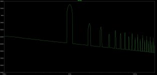
After the ancient NHB-108 model one, the newer LHC-108 and CTH-8550 amps contain the 458's circuit with 2 pair of MJL1302A/MJL3281A. To suppose the NHB-108 model two includes a similar one is logical but there is no exact information...I have two clones of the original, both built with pretty much the same parts. Most importantly i have used the same PS. Along these lines the comparison between 1 and 2 is not even remotely in favour of 2, especially into 4ohm loads. The way the sound roughens up with volume is something the original does not do. Harmonics up the the 20th are evident. The 2 also has lower OLG, so this is by no means surprising. The idea that the same circuit is used to produce 100v peaks in the 458 appears a bit shaky to me.
You may think the key of darTZeel magic is the schematic and the spectrum of THD.
The real magic is the synergy between the circuit and the "sound" of certain parts which are used by dartzeel.
If you change a resistor from Dale RN55 to Beyschlag MBB/SMA0207, you cannot measure any difference concerning THD, etc. But you can hear difference and you may step into the real dartzeel sound's direction...
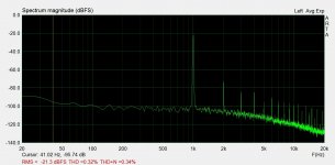
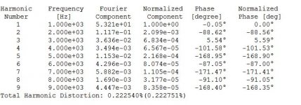
My 458 circuit's THD:
39,3Veff / 8,2Ohm ( 188W ) / 1kHz - THD=0,085%
38,8Veff / 4Ohm ( 376W ) / 1kHz - THD=0,11%
and I use this amp with a speaker which has 2.5Ohms impedance minimum.
Attachments
My 458 circuit's THD:
39,3Veff / 8,2Ohm ( 188W ) / 1kHz - THD=0,085%
Which seems in line with the published measurements for the 458. Have you measured the distortion spectrum at some more usable power range? Perhaps 5 - 50W?
Come to think of it i have mostly heard the original 458 at extreme power levels, where its distortion is minimal.
Attachments

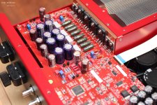
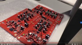
Part of the explaination for Ver2 result may be that some part of the amp schematic is located on the protection PCB, in fact extending the already amp small foot print. That may be the way they were able to squeeze to 458 circuit into the 108 frame. Looking at the ver2 protection PCB we can see it is using smd part, but more important look at the left section where a new connector is added. We can see BCP52, BCP53 smd transistors, and added parts. Maybe there is a first gain stage on this section than it goes to the final output pcb... Just a tought...
Attachments

My 458 circuit's THD:
39,3Veff / 8,2Ohm ( 188W ) / 1kHz - THD=0,085%
It is perhaps useful to specify which circuit achieves this: your original idea, or some of the later ones with a cascode and other improvements?
Your initial circuit seems to have a much higher distortion.
My 458 circuit:
https://www.diyaudio.com/forums/solid-state/134362-dartzeel-amp-schematic-build-68.html#post6180802
All my other schematics with cascode, NFB, etc are only plans, simulations.
Here, you can look at the HD ( 120mW / 8Ohms ) with different bias current:
audiodiyers.hu • Tema megtekintese - darTZeel erősitők
180W/8ohms/1kHz.
The simulation is close to what i measured. Not very pretty.
The Stereophile measurement with the gradually decreasing with output power distortion is impossible to replicate.
I get you idea: the amp ugly distortion is compensated by mellow sounding passive parts. Not sure i can swallow it.
The simulation is close to what i measured. Not very pretty.
The Stereophile measurement with the gradually decreasing with output power distortion is impossible to replicate.
I get you idea: the amp ugly distortion is compensated by mellow sounding passive parts. Not sure i can swallow it.
Attachments
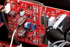
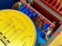
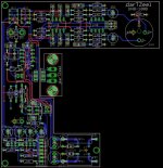
Nearly finnished Dartzeel.
R102 and 101 is 110 kohm. Placed an parrallel with input resistor 51 kohm. Now Total bias from 230 vac is 0.5 A. One channel warmer then the other and I wonder why. DC out is fine. There is some AC at output. Input parralel by testing is 600 ohm. Hope it will be ok when I use a Pre at input. Maybe I should ad a input buffer if there is to much noise. I will let it warm until it's morning.
R102 and 101 is 110 kohm. Placed an parrallel with input resistor 51 kohm. Now Total bias from 230 vac is 0.5 A. One channel warmer then the other and I wonder why. DC out is fine. There is some AC at output. Input parralel by testing is 600 ohm. Hope it will be ok when I use a Pre at input. Maybe I should ad a input buffer if there is to much noise. I will let it warm until it's morning.
Anybody know about C3 and 4. In the warm channel I have used polystyren and in the not so warm Ceramic. I wonder if there is an explanation. Maybe I should change to ceramic.
..." Looking at the ver2 protection PCB we can see it is using smd part, but more important look at the left section where a new connector is added. We can see BCP52, BCP53 smd transistors, and added parts. Maybe there is a first gain stage on this section than it goes to the final output pcb... Just a tought...
AND does this not look like a multilayer pcb?? Even more difficult to descipher 🙁
Attachments
Last edited:
Maybe just 2mm thickness, like the amp pcb... But indeed impossible to figure the actual circuit with just a few pictures...
Maybe just 2mm thickness, like the amp pcb... But indeed impossible to figure the actual circuit with just a few pictures...
I don’t think there is some magic circuit for the amp on this board because I read somewhere you could upgrade from model one to two without the new protection board if your model one was of later date with SNCP ad on.
Also the new update is using the new solid core silver wire from the input to amp board and on the pictures from the new protection board I can’t see this wire.
There were more steps, price’s for the upgrade.
Anybody know about C3 and 4.
Your issue has nothing to do with the caps. The level of bias depends on the zeners, the transistors current gains and the base stopper resistors. Please take measurements and publish the voltage drops across R19/R20 in both channels. This is just to make sure all the zeners are identical. If they are then the difference in bias is due to different current gain of the output transistors. Have you matched those in any way? What is your rail voltage?
Total bias from 230 vac is 0.5 A.
You probably mean current consumption, not bias. Is that per channel, measured at the transformer primary?
What you need is to put some more meaningful numbers on the current draw. Put a 1ohm resistor between each amp board positive rail and the + of the DC power supply and measure the voltage drop across.

- Home
- Amplifiers
- Solid State
- Dartzeel amp schematic - build this?