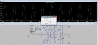
Here with bypass caps, and input 10uF... need to make a spice of that to check parts... CCS supply seems to be from a drop resisto and zener since no extra 5V power supply seems to be connected to the PCB... Like this?
Attachments

Last edited:
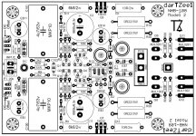
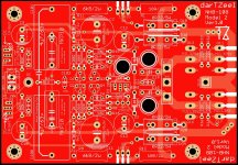
Great! by the look of it there is two large red Wima cap, 2x4.7u in parallel? Indeed we can see 'Z2' just beside C4, so certainly a zener there.
Can't see the zero adj pot on the original, do you think it is still necessary with the two AVX Supercap in the feedback?
Also there are the two small 47uF/100v caps, probably one at the 6800u cap V+ to gnd, and the other at the PSU input pads, with the two MKS4 film caps, not needed with the SPice, but probably there to filter the PCU
SB
Last edited:
Can't see the zero adj pot on the original, do you think it is still necessary with the two AVX Supercap in the feedback?
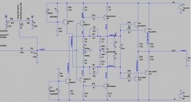
An interesting question. If you remove the offset setting network you need to provide a biasing resistor at the input to ground. The offset then becomes dependent upon that resistor value. In the current simulation a 60k resistor between the input bases and ground minimises the offset.
An even more interesting question is whether the amp will sound the same. In my 108 it does not and i suspect the reason is the poor grounding arrangement of the original amp - something Domenico often complains about.
The offset network is providing a virtual ground reference derived between the ps rails and this is clearly preferable to using the ground plane at input. If the pcb is layed out with proper attention to grounding and circulating currents the result may be different.
Where does that leave us? I would prefer to keep the offset circuit as i am uncertain in my abilities and patience to lay out the ground on the board properly.
Make sense, will keep it then. There is a possibility it is near the side of the pcb, and we don't see it...
SB
SB
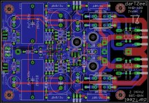
This looks pretty close to what could be gleaned from the board pics. But why two input caps?
Is it possible to also get a 5mm spacing option for the emitter resistors (Caddocks)?
Is it possible to also get a 5mm spacing option for the emitter resistors (Caddocks)?
Last edited:
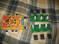
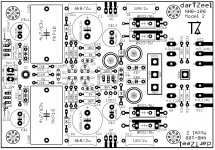
Yes no problem, check the picture... Alos we can use the two most excentric cap holes and install a nice axial film cap instead of the stacked Wima film..
BTW the Ver2 pcb transistors matched the Ver1 location, so it could be easier to mount either of them using the same heatsink threaded holes...
SB
BTW the Ver2 pcb transistors matched the Ver1 location, so it could be easier to mount either of them using the same heatsink threaded holes...
SB
Attachments

Always possible 🙂 but need to find appropriate heatsink to fit in there. Also I wouldn't use 6.8mF instead 1.0 to 2.2mF bypassed with high quality pp film (Panasonic ECW series with 10mm pitch at 1.0uF) exampleIs it possible to also get a 5mm spacing option for the emitter resistors (Caddocks)?
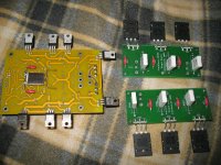
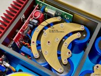
Just a thought. Twist caddocks 90 degrees and mount on one heatsink back to back. 9100 without heatsink rated only to 3.5W, 930 even less. Futaba's will benefit from twisting also. Option for the caddocks - mounting under pcb with elastic spacer to press it against main heatsinkHere provision for emittor resistor Caddock MP9100 and Metal element MPC74 type resistors
9100 without heatsink rated only to 3.5W, 930 even less.
Not sure this is a problem. Even at full power using a sinewave this figure is not exceeded and at anything resembling normal listening to music, not sinewaves it is much less than a watt.
It is not worth complicating the routing as very few people are likely to use the Caddocks anyway.
Last edited:
On a layout I modified for original dartzeel (with split resistor) that twist rather simplified routing. but I dont see a single reason not to use it if it is possible. Cost of parts on a board including Caddocks is still negligible comparing to the cost of power supply.It is not worth complicating the routing as very few people are likely to use the Caddocks anyway.
Last edited:
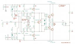
Here is what i think the circuit should look like. Zeners are for 5v1 and outputs are running 100mA each.
Sorry, zeners are 4.7v as shown in the circuit. For 5v1 zeners the emitter resistors need to be changed to 2k4.
- Home
- Amplifiers
- Solid State
- Dartzeel amp schematic - build this?