I was told in this forum to change from 5.1 to 6.2 v Zeners!
Must have missed this one. Best zener voltage for temperature stability used to be 5.6v but with more recent devices this does not seem very important.
The 108 series 1 used a 5v1 zener, so chances are they bought a lot and used the same in series 2 🙂
@Algar_emi, @analog_SA, @garrbage
Great to read conversation among 3 experts! Thanks guys.
One question:
The board on the recent post (#1020) was labeled:
darTZel NHB-108 Model 2, Ver 1.
Will that board eventually be available for group purchase? In that case I will be the 1st in the queue. I would like very much to have an amplifier based on board developed here.
Cheers guys!
 🙂
🙂
Great to read conversation among 3 experts! Thanks guys.
One question:
The board on the recent post (#1020) was labeled:
darTZel NHB-108 Model 2, Ver 1.
Will that board eventually be available for group purchase? In that case I will be the 1st in the queue. I would like very much to have an amplifier based on board developed here.
Cheers guys!
🙂@Algar_emi, @analog_SA, @garrbage
Great to read conversation among 3 experts! Thanks guys.
One question:
The board on the recent post (#1020) was labeled:
darTZel NHB-108 Model 2, Ver 1.
Will that board eventually be available for group purchase? In that case I will be the 1st in the queue. I would like very much to have an amplifier based on board developed here.
Cheers guys!
I want the boards also
Good work guys🙂
I'm also in for group purchase on model 2.
Many thanks, keep on the fantastic work🙂🙂🙂
I'm also in for group purchase on model 2.
Many thanks, keep on the fantastic work🙂🙂🙂
Maybe better to wait and see (hear 😉 ) if this ver2 prototype is working and deliver good result. Don't forget we don't know the ver2 actual circuit, we just assumed and guess...
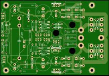
Guessing analog_sa will be the first to try it. I'll sell the few extra I'll get so some others can try it, but no warranty it will work ok, and sound good. It may be too soon for a GB, don't want to send to a lot of buyer a defective pcb...
With that in mind, if you still want to try it, send me a private email. BTW the pcb will be the usual 1oz copper, 1.6mm thickness to start. If the pcb deliver and i start a GB, then we can order 2oz copper.
BTW my board already have double top/bottom output traces that equal to 2oz... So proceed with caution when you'll test it...
Let me know and keep in mind it is a prototype...
SB
Last edited:
Exactly that is fun.Let me know and keep in mind it is a prototype...
SB
For me it will sound the best in the world because it comes from friends, from efforts of this great community. I would like two: Black Board of our friend @garrbage and Ver2 from @Algar_emi.
Guys keep making this tread great 🙂
I can lend you my extra pair and you return it when yours arrive. I have a pair of bare PCBs and we aren't faraway. Just send me a PM.My PCB from China have not yet arrived ( 40 days )
Last edited:
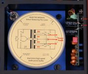
With the help of some other members that are fortunate enough to have the real thing, here some of our findings. Also after reading some more I can figure a fewextra things.
Stereophile mentioned solid state relays for the softstart and power on, so no click as reported, let's assume a simple 2P4T switch for the secondaries volt selection (from picture simple NKK toggle 4PDT, 125V, 6A switch)
Also the transfo primaries voltage selection switch on newer model seems to be a Shurter, again rated at 250V, 6.3Amp
From the manual and transfo label with knows that the fuses are 6.3A/115V and 3.15A/230V, so it makes sense that the Volt selector capacit matches the highest rated fuse of 6.3A
At startup the real amp behavior is:
-There is no relay clicking when power on and off --> confirm Solid state relays
-There is a really, really small pop in the speakers when turned on --> direct output, amp stabilized rapidly and small dc offset, hence the 'pop'
-The amplifier plays an half minute after switch off --> the large supply caps discharge slowly and the amp continue to work until they are empty.
-There is a small relay click when switching between XLR, Phono and 50ohm, a small 15V TP is near the relay, No 15 VDC on the input board in off state --> so this 15V comes from the protection PCB
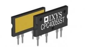
Found very nice solid-state relay from IXYS, pcb mount, small as a rectifier. If bolted to the bottom frame can pass 20A. So the Power-on and softstart relay can be on small pcb right under the pcb...
No DC voltage on the power capacitors in off state --> so there is no small 5V capacitor bias voltage after all...
Under the main transformers is there another blue PCB transformer on an PCB --> Probably the standby transformer, maybe from Amgis
The input boards have no components on the back, so as I can see the Neutrik transformers is alone --> the Neutrik transfo is used <as is>, no extra parts on the input...
The controller board is not powered in off state--> maybe powered directly from the amp rails?
Internal wiring seems to be Kimber KCAG and TCX hookup wire
So from all these we can probably assume:
-Before we press the Power-on front button, only the standby transfo is powered, then then one solid state relay start the amp, and after a small delay the other soft-start solid state relay bypass the inline resistor. From Stereophile we know that this resistor is probably the usual Dale RH Series, metal body, probably bolted to the amp bottom for heat dissipation.
-Overtemp NC switch (70C) in series with the power-on solid state relay control line will turn off the amp in case of Overtemp...
-Pretty sure the designer mentioned a servo for DC offset correction was in the Model one, probably the ic and parts on the bottom of the input card. There is a jumper to disable this DC compensation to be added to the input signal. The 'B' upgrade with the super cap, the 'DC Comp' is not there, so the servo is not used...
-Current sensing PCB: Sensor is LEM LA55-P, two small Wima caps are there, probably local bypass for the +/-15V supply from protection pcb. This small pcb is connected by 4 wires, probably +-15V, GND and current sensor output...
Then 3 wires goes to the rear pcb probably +-15V and gnd supplies
Protection Card
-Again the Protection PCB is off when the amp is of, there is a possibility it is power directly from the Amp rails... Local supply are +/-15V using the usual 7815 and 7915 regs bolted to the heatsink.
-Amp output sample is taken directly at the Red output wire on the amp car with a smaller yel wire, twisted around the red. The yel wire goes up to the current sensing relay and from there up to the protection card.
On the protection Card, maybe the protection is similar to the Goldmund amp that have a lot of TL07CN Comparators IC.
-This protection usually includes a DC detection + HF oscillation detection (for oscillation), combined with a OR gate = one shutdown fault --> Crowbar
-Simple op-amp conditioning for the current sensor (like Goldmund again), overcurrent being a fail condition as well...
-Then three level comparators for Led:
>>If no input signal (<10mW into 8ohms at output), for 45sec, then turn ON led, LOW intensity
>>Signal presence (>10mW into 8ohms at output), then turn ON led, MEDIUM intensity
>>Amp reach its maximum power (near clipping). Flash led for 1sec at HIGH intensity, then get back to MEDIUM, wait at least 1 sec before flashing again if power still reach maximum
and Clipping protection, so goes too high (clipping) shutdown the amp (Crowbar)
The protection PCB has three trimmers, and three test points VA-I, VA-V and GND, I is probably Current crowbar trigger point, same for V that is probably clipping crowbar...
-From pictures small TO92 transistors seems to be the same as used on the amp, 2N5401 and 2N5551 (makes sense, they probably have tons of them...)
Stereophile mentioned solid state relays for the softstart and power on, so no click as reported, let's assume a simple 2P4T switch for the secondaries volt selection (from picture simple NKK toggle 4PDT, 125V, 6A switch)
Also the transfo primaries voltage selection switch on newer model seems to be a Shurter, again rated at 250V, 6.3Amp
From the manual and transfo label with knows that the fuses are 6.3A/115V and 3.15A/230V, so it makes sense that the Volt selector capacit matches the highest rated fuse of 6.3A
At startup the real amp behavior is:
-There is no relay clicking when power on and off --> confirm Solid state relays
-There is a really, really small pop in the speakers when turned on --> direct output, amp stabilized rapidly and small dc offset, hence the 'pop'
-The amplifier plays an half minute after switch off --> the large supply caps discharge slowly and the amp continue to work until they are empty.
-There is a small relay click when switching between XLR, Phono and 50ohm, a small 15V TP is near the relay, No 15 VDC on the input board in off state --> so this 15V comes from the protection PCB
Found very nice solid-state relay from IXYS, pcb mount, small as a rectifier. If bolted to the bottom frame can pass 20A. So the Power-on and softstart relay can be on small pcb right under the pcb...
No DC voltage on the power capacitors in off state --> so there is no small 5V capacitor bias voltage after all...
Under the main transformers is there another blue PCB transformer on an PCB --> Probably the standby transformer, maybe from Amgis
The input boards have no components on the back, so as I can see the Neutrik transformers is alone --> the Neutrik transfo is used <as is>, no extra parts on the input...
The controller board is not powered in off state--> maybe powered directly from the amp rails?
Internal wiring seems to be Kimber KCAG and TCX hookup wire
So from all these we can probably assume:
-Before we press the Power-on front button, only the standby transfo is powered, then then one solid state relay start the amp, and after a small delay the other soft-start solid state relay bypass the inline resistor. From Stereophile we know that this resistor is probably the usual Dale RH Series, metal body, probably bolted to the amp bottom for heat dissipation.
-Overtemp NC switch (70C) in series with the power-on solid state relay control line will turn off the amp in case of Overtemp...
-Pretty sure the designer mentioned a servo for DC offset correction was in the Model one, probably the ic and parts on the bottom of the input card. There is a jumper to disable this DC compensation to be added to the input signal. The 'B' upgrade with the super cap, the 'DC Comp' is not there, so the servo is not used...
-Current sensing PCB: Sensor is LEM LA55-P, two small Wima caps are there, probably local bypass for the +/-15V supply from protection pcb. This small pcb is connected by 4 wires, probably +-15V, GND and current sensor output...
Then 3 wires goes to the rear pcb probably +-15V and gnd supplies
Protection Card
-Again the Protection PCB is off when the amp is of, there is a possibility it is power directly from the Amp rails... Local supply are +/-15V using the usual 7815 and 7915 regs bolted to the heatsink.
-Amp output sample is taken directly at the Red output wire on the amp car with a smaller yel wire, twisted around the red. The yel wire goes up to the current sensing relay and from there up to the protection card.
On the protection Card, maybe the protection is similar to the Goldmund amp that have a lot of TL07CN Comparators IC.
-This protection usually includes a DC detection + HF oscillation detection (for oscillation), combined with a OR gate = one shutdown fault --> Crowbar
-Simple op-amp conditioning for the current sensor (like Goldmund again), overcurrent being a fail condition as well...
-Then three level comparators for Led:
>>If no input signal (<10mW into 8ohms at output), for 45sec, then turn ON led, LOW intensity
>>Signal presence (>10mW into 8ohms at output), then turn ON led, MEDIUM intensity
>>Amp reach its maximum power (near clipping). Flash led for 1sec at HIGH intensity, then get back to MEDIUM, wait at least 1 sec before flashing again if power still reach maximum
and Clipping protection, so goes too high (clipping) shutdown the amp (Crowbar)
The protection PCB has three trimmers, and three test points VA-I, VA-V and GND, I is probably Current crowbar trigger point, same for V that is probably clipping crowbar...
-From pictures small TO92 transistors seems to be the same as used on the amp, 2N5401 and 2N5551 (makes sense, they probably have tons of them...)
Last edited:
Great detective work SB!
Do you have reasons to believe the SS relay is a factory made device? I would be very surprised.
Do you have reasons to believe the SS relay is a factory made device? I would be very surprised.
Here the Goldmund Current sensor conditionning and Fault, and the DC Voltage and HF oscillation, also an other fault... OR Gate on these schematics can be done using simple diode 'OR'...
Attachments
Last edited:
Not at all, sorry if I implied that. I found this great SS relay from IXYS 849-CPC1918J, 13A, at Mouser but there is also a 20A version, but sadly not in stock. At 14$CAN it is not that expensive, fit the small pcb under the transfo, and can be mounted on the metal plate under the transfo for heat dissipation. Can be control directly by a dc voltage.
Attachments
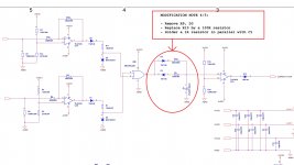
Latest findings, the monitoring PCB raw supply before the +15 regs is around 20Vdc (19Vac x 1.4142)-1.4V rectifier drops = 25Vdc, not bad as input for the 7815 series regs. Maybe there are some dropout resistors to reduce the voltage to 20Vdc... So there is a storng possibility it is derived directly from the inner seocndaries of the amp main transformer. Since these secondaries always remains at the same voltage whatever is the transfo is switch from 8ohms or 4ohms mode, it make sense to supply from the fix section of the transfo...
Attachments
Latest findings, the monitoring PCB raw supply before the +15 regs is around 20Vdc (19Vac x 1.4142)-1.4V rectifier drops = 25Vdc, not bad as input for the 7815 series regs. Maybe there are some dropout resistors to reduce the voltage to 20Vdc... So there is a storng possibility it is derived directly from the inner seocndaries of the amp main transformer. Since these secondaries always remains at the same voltage whatever is the transfo is switch from 8ohms or 4ohms mode, it make sense to supply from the fix section of the transfo...
Somewhere I read version 2 (or possibly a later model) has a small, separate transformer for the standby power, according to a manual (or maybe in a comment by Mr Deletraz in Stereophile)
Surely it is not desirable to take the standby power from the main transformer.
The protection pcb only is powered by the main transfo, not the standby section. And this section indeed is powered by a separate small transformer that includes two static relays, on for Power-On, the other for Softstart. The temperature sensor on the heatsink is directly inline with the Power-On, stop the amp in case of overheat and resume operation when cold down occurs...
The protection PCB is not powered when the amp is off, only the standby section remained, so it doesn't appear that the protection pcb is involved with the power-on and/or the softstart section...
The Standby transfo and power supply, Power-On circuit and softstart are located under the power transformer, on separate small pcb...
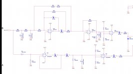
Here a concept diagram of the amp, with control, protection, Power supplies and input pcb...
The protection PCB is not powered when the amp is off, only the standby section remained, so it doesn't appear that the protection pcb is involved with the power-on and/or the softstart section...
The Standby transfo and power supply, Power-On circuit and softstart are located under the power transformer, on separate small pcb...
Here a concept diagram of the amp, with control, protection, Power supplies and input pcb...
Attachments
Great. Your protection schematic is awesome!
I misunderstood you regarding the standby power, sorry, I was only trying to be helpful.
I misunderstood you regarding the standby power, sorry, I was only trying to be helpful.
Last edited:
What is probably needed is also some delay at power-on, and why not an other delay on the rear input pcb, to switch the input relay only after some delay, kind of input mute... And some power supplies monitoring, can be the input delay, no fault alarm until both protect and power supplies voltages are stabilized...
- Home
- Amplifiers
- Solid State
- Dartzeel amp schematic - build this?