OK! You're an expert and I'm a noob, but tell me what is advantage of these wirewound resistors which, if you admitt or not, bring adittional inductance into the amplifier? And is that desirable or not?🙂Uh, what?
What have resistors to do with a board layout? Sorry, don't get it. Which specific resistors do you have in mind?
6K8/5W and 4K7/2W.What have resistors to do with a board layout? Sorry, don't get it. Which specific resistors do you have in mind?
Meanwhile I have verified on Farnell that there are metal oxide resistors but I'm not sure if these are adequate for this purpose. I have hesitated which resistors to choose and I've concluded that Vishay metal film could be the right choice but there are no metal film for these two resistances. So I have reluctantly decided to use wirewound. Perhaps that was wrong decisisn, but as usually, I am a positive person who wants to improve decisions and to share them with my friends here.
So, could you please help me to make the right decisions on these two resistors? Metal oxide film or Wirewound?
And, by the way: I wish you a pleasant Sunday evening.
Desejo-lhe uma agradável noite de domingo.
🙂🙂
So, this has nothing to do with Garrbage's board then?
I prefer using MF resistors everywhere. For high power Caddock thick film MP series, for less demanding high power applications non inductive Mills. Metal oxide is generally not to my taste.
In my 108 clones i don't use any big resistors. The 4.7k dissipates 355mW and the 6.8k - 380mW. In both positions i think i have 1W metal films.
The 6,8k resistor is probably not very audible and a MO may be just fine. The 4.7k otoh may be extremely audible.
Sorry, forgot you were asking for a choice between WW and MO.
In this particular instance there is no issue with the 4.7k being inductive. On the contrary, the more inductance, the merrier 🙂 The 6.8k should be non inductive so a MO is fine.
Unless you forget about the excessive wattage ratings and go for 1W MF.
Last edited:
Selfy,Wirewounds are not made equal 😀
I'm glad to see you here arround. We have here very pleasant conversation and I'm looking forward to hear from you more often.🙂 We would need your expert advice.
Last edited:
@Analog_sa,
Again, you have helped me. I will replace these four large wirewounds with 1W MF. See, I do not fear from putting sometimes supid questions because it results in something usefull and pleasant because I lure the best from people arround me.
Let me tell you a story which really happened. Once I took part in an expert meeting where we were supposed to solve important problem. One of "blue-collar" participants has started to talk but the big boss stopped him with almost telling him "Shut up, What do you know?". After the meeting I went to that "blue-collar" man and told him: "My appologies, I didn't like that what happened at all and I beleive you have something important to say". Then, what he told me was a clear and correct solution of the problem. I said to myself: "I'm lucky because I respect all people arround me and ask them a question if I do not have the correct answer."
What I wanted to say is: We can solve the problems only if we are prepared to say: "I don't understand, please, help me. And I'm not a noob, I have achieved some things in my life and have published original scientific works in the best magazines, but in quite another science. Yet, I don't hesitate to ask "stupid questions".
Thanks Analog_sa for helping me with answer to my stupid question.
I indeed appreciate that.
Boa noite meu querido amigo. 🙂
Last edited:
I will post more info of this board when I have some free time. Making speaker ground connection on the boar do not require to connect it there 🙂 in the final assembled stage but it makes it easier to connect load to the board while tuning.Btw, not sure if this has been discussed in the thread, but the original 108 does not connect the speaker return to the ground terminal on board but instead to the capacitor bank. It makes a subtle but worthwhile improvement.
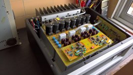
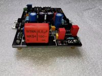
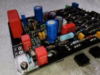
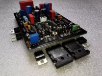
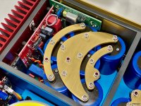
I don't like the sound of pte caps, so caps footprints accept pp caps (mostly Wima/Panasonic) also I don't like wire wound resistors on the boards, so I split it in two and used 2W Dale resistors. Resistors used mostly metalfilm Dale and PRP. Also I use few cmd parts where I found it fit (zenners are on the bottom side).
Input cap.... I have a bag of nice sounding 6.8uf pp caps marked TI with pitch of 30mm (strange I know) unfortunately I put it in one of the boxes in storage and seam I cannot locate that particular box. Board was ordered with 105um (3oz) copper to further lower trace impedance. It worked nicely but one need to have real good soldering station to solder anything to the ground and output on that board 🙂 soldering output spades particularly was interesting experience 🙂
Attachments
Last edited:
The 3oz copper is indeed very nice. Is it not too expensive for a small run? Or was it not a small run? 🙂
The splitting of resistors was a great idea.
Not sure i like the input part using the ground plane as a ground return but my boards are the same.
The splitting of resistors was a great idea.
Not sure i like the input part using the ground plane as a ground return but my boards are the same.
I do not mind the wirewound resistors, but I've come to the conclusion they sound very different depending on the material of the wire used. Some sound awful, some are really great soundwise. Most of them are inductive, but there are a lot of places where this doesn't much matter. My wirewound resistors of choice, depending on the budget and available space, are: Mills, Ohimte AG, Sfernice RWM, Welwyn WP-S.
Speaking of darTZeel resistor types I would recommend using audiophile parts only outside the NFB loop and for the FB network itself. I am using metal film Takmans at the input and for the 56K values (mine are 47K but I run the amp at ±40V). For the NFB resistors I use Caddock MK132, which is probably an overkill, but I had them in stock for another project. For the 4.7K for zeners I use RWMs. For the rest I use general purpose metal film resistors.
However I find some power ratings in the "original" schematic really odd. I guess Herve chose them based on listening the actual amp. The 7.5K resistors in the NFB should be 0.5W to be on the safe side. The 39R resistors of the current sources dissipate about half a watt, and choosing a 2W resistor would be quite enough.
PS: Some people are against putting large lytics on the amp board. The reason for this being that some rectifying currents start to flow through them...
Last edited:
The reason for this being that some rectifying currents start to flow through them...
Yes, the current loops have to be very tightly defined. But i assume the main PS caps are off board in Garrbage's design, what we see here is just to provide a low impedance close to the load.
The best example how to do this right are perhaps the Spectral amps where each output transistor gets its own transformer winding, rectifier and cap. Even the parallel transistors!
Tempting to try this out with LT4320 rectifiers 😀
Attachments
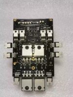
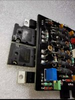
Here is what I found on a russian forum, they called it 'Ver2' pcb, and from the look of it seems to be similar to the original Dartzeel ver2 pcb. Maybe they got some info on it... It has the other transistor under the pcb, and it seems to have 4 final transistors...
SB
SB
Attachments
Small. 16 first + 10 later within 12 months they agreed to do without tooling. It is visibly more expensive than 2oz, not every pcb shop can do copper over 2oz so choices are somewhat limited. But it still peanuts comparing to the whole cost.The 3oz copper is indeed very nice. Is it not too expensive for a small run? Or was it not a small run? 🙂
Non inductive non magnetic is my choice when I need to use wire-wound, but difficulty obtaining them with such properties and of required value kinda turning me away.I do not mind the wirewound resistors, but I've come to the conclusion they sound very different depending on the material of the wire used. Some sound awful, some are really great soundwise. Most of them are inductive, but there are a lot of places where this doesn't much matter. My wirewound resistors of choice, depending on the budget and available space, are: Mills, Ohimte AG, Sfernice RWM, Welwyn WP-S.
Speaking of darTZeel resistor types I would recommend using audiophile parts only outside the NFB loop and for the FB network itself. I am using metal film Takmans at the input and for the 56K values (mine are 47K but I run the amp at ±40V). For the NFB resistors I use Caddock MK132, which is probably an overkill, but I had them in stock for another project. For the 4.7K for zeners I use RWMs. For the rest I use general purpose metal film resistors.
However I find some power ratings in the "original" schematic really odd. I guess Herve chose them based on listening the actual amp. The 7.5K resistors in the NFB should be 0.5W to be on the safe side. The 39R resistors of the current sources dissipate about half a watt, and choosing a 2W resistor would be quite enough.
:facepalm: no commentPS: Some people are against putting large lytics on the amp board. The reason for this being that some rectifying currents start to flow through them...
Last edited:
They don't as it became clear from the discussion. Just somebody decided to gain on popularity of the original design. And as far, as it was discussed on the one of the largest russian techno forums, this design have nothing to do with Dartzeel ver2 original. Unfortunately the topic where it was discussed was heavily edited so not sure if it can be found.Here is what I found on a russian forum, they called it 'Ver2' pcb, and from the look of it seems to be similar to the original Dartzeel ver2 pcb. Maybe they got some info on it... It has the other transistor under the pcb, and it seems to have 4 final transistors...
SB
You are correct main caps are off board.Yes, the current loops have to be very tightly defined. But i assume the main PS caps are off board in Garrbage's design, what we see here is just to provide a low impedance close to the load.
Last edited:
Here is what I found on a russian forum, they called it 'Ver2' pcb...
SB
This is not the second version.
The real version looks different.
Attachments
Yes, the current loops have to be very tightly defined. But i assume the main PS caps are off board in Garrbage's design, what we see here is just to provide a low impedance close to the load.
The best example how to do this right are perhaps the Spectral amps where each output transistor gets its own transformer winding, rectifier and cap. Even the parallel transistors!
Tempting to try this out with LT4320 rectifiers 😀
okay the Spectral power supplies, but the oddity is those polarization trimmers, one every single mosfet
strange using mosfets:
I can understand transistors, but mosfets ........
The non-selection of mosfets has little or nothing to do with it
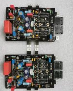
Take note that I'll order a small batch of the DartZeel PCB, 2mm thickness & 2oz copper for me and an other forum member. This is the original design, see my previous post...
Let me know if interested, if they are not sold I'll post them on the Swaap Meet once I'll receive them. I don't expect to do a GB with these, I may have only 1 or 2 extra pairs to sell...
BTW anyone knows what are the rubber pcb standoff isolator that DartZeel is using, see picture?
Thanks
SB
Let me know if interested, if they are not sold I'll post them on the Swaap Meet once I'll receive them. I don't expect to do a GB with these, I may have only 1 or 2 extra pairs to sell...
BTW anyone knows what are the rubber pcb standoff isolator that DartZeel is using, see picture?
Thanks
SB
Attachments

Last edited:
Would this work as an alternative DC speaker protection solution with the nhb 108 clone board?
Ready-to-Run (RTR) SSR DC Speaker Protection and Delay GB
Ready-to-Run (RTR) SSR DC Speaker Protection and Delay GB
Last edited:
- Home
- Amplifiers
- Solid State
- Dartzeel amp schematic - build this?