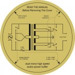
The 5V bias (not 2V sorry) was mentionned in the Dartzeel_nhb-108_model_1_technical_en manual, section 9.1, page 24 of 28. Here an extract of the manual...
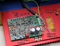
The SCR has probably to be on the transformer secondary, to discharge rapidly the supply caps, and that translate to the primary as an overload, that blow the fuse...
Indeed a small standby transformer would be more elegant, and will keep the monitoring pcb active. On top of that the protection pcb doesn't show large power voltage drop resistor before the small rectifier diodes, indicating that this pcb is indeed supplied by a smaller voltage transformer. Under the transformer there is indeed enough space to insert a small split core standy by transfo...
SB
Attachments

Last edited:
AFAIK crowbar in 108 does the same. The reason for it:
You seem to be in an argumentative mood today 🙂
Despite your reasoning the 108 does not behave the way you want it 😎 Below is a quote from the manual explaining this.
It is a result of both the desire to avoid fuses where they would very audible and also of practicality: whenever there is an overload condition the user has to replace the one and only fuse. The absence of DC rail fuses is also clear from the internal pics.
Attachments
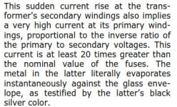
What other secondaries are relevant at this point? And why it is relevant at the time when you output transistors just went in smoke? There is only one thing left to do at that moment - protect the speakers. And yes, there is enough time to blow even inexpensive fuses not too inexpensive as short current must be limited to protect caps (no more then ripple current for given caps). Also the fuses usually blown in tens to a hundred of milliseconds (decent ones rated for 10A-16A - single digits @100A), IMHO that should have no effect on any properly designed power supply connected to other secondaries on a same transformer if they exist.Shorting the output will lead to a collapse in the magnetic flux that will affect all other secondaries. Will the SCR remain triggered for long enough for the fuses to blow under such conditions?
Also I always use separate transformer for protection circuit and standby.
As the main purpose for this circuit is - protecting speakers. It is as clean as possible. If someone doesn't like the idea of triac connected in parallel to the output it can be replaced with a mechanical relay with only contact requirement "make" "do not brake" such relay would be replaced with fuses so the socket mounted preferable.Maybe it can be made to work but it doesn't seem like a very clean solution.
OK but where then the charge go caps where charged before output transistors blown output is shorted (main fuse is blown) but what happening with the rail caps. How they are discharging? trough the short? I used the 2 1Ohm 50W resistors as a crowbar so you are saying this is all it is. They were running to hot to my liking in experiments. I also do not like to fine tune soft start to that levelYou seem to be in an argumentative mood today 🙂
Despite your reasoning the 108 does not behave the way you want it 😎 Below is a quote from the manual explaining this.
It is a result of both the desire to avoid fuses where they would very audible and also of practicality: whenever there is an overload condition the user has to replace the one and only fuse. The absence of DC rail fuses is also clear from the internal pics.
Last edited:
I think it cannot be that during each accident it is necessary to change not only the fuse but also the output transistors, when I read the description of the amplifier, it was said that only the fuse was replaced, or I did not understand anything.
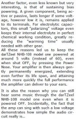
[About the "bang": The amp has power resistors in series with the AC mains, for soft starting purpose. These resistors are then shunted by a static relay (there are two static relays in the amp, one for the power on, the other for soft start; the main switch does not carry the power by itself).
In very earlier versions (only four samples made this way, none sold to end users), the circuit which feeds the static relay was powered by one of the two main power transformers. When you had one channel shut off by the crowbar circuit, the static relay was no more activated, and the power resistors saw full power, and literally exploded (they are in metallic-kind cans, and are true weapons when heated too quickly).
Current versions use a third, small separate transformer, located under the left power transformer platform, dedicated to the soft start circuit, so when only one channel is shut off, the static relay is still activated.]
Sure 🙂 analog_sa is right original amp blows main fuse. I just don't like that idea and dismissed at the start. Blowing rail fuses makes more sense to me and I didn't think it twice as it is more less standard solution for amps with high (>50-55 Volts) rail voltage. Also I as many others was never able to detect fuses in the supply rails. When I have time I will run some tests to if I can do that to my liking. I guess splitting the primary wiring to go to each transformer through separate fuse should help but in this case it needs to be 2 separate soft start circuits one for each transformer after the fuse. Or one common fuse before single soft start selecting that given all the circumstances a bit of pain.
I' m surprised that first version ever made itself out of testing bench (it just plain lame). there is always addition of thermal breaker on the crowbar/brake resistors to prevent such issues, or there is a process of selecting primary slow blow fuse rating to prevent such things, the latter is not that simple.Current versions use a third, small separate transformer
Last edited:
What other secondaries are relevant at this point? And why it is relevant at the time when you output transistors just went in smoke?
Perhaps you were not following but this was a response to Algar Emi's hypothesis that there is no supplementary transformer for the protection circuit and it was powered up from a separate winding on the main transformer.
My reasoning was that once the SCR is activated, the PS for the protection will also disappear and this may happen before the fuse has blown, therefore resetting the SCR and rendering the protection ineffective.
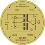
Your questions re the main caps discharging are appropriate but do not change the fact that the 108 is designed like that. If you don't like it then do it differently, i was only pointing out how the protection circuit works without speculating - it is all there in the manual.
Obviously there needs to be a resistor limiting the current to the max the caps can take without boiling or melting.
The Stereophile test mishap was graciously explained by not fitting the right fuse but i have my doubts.
I agree with you that this type of protection should only be activated as a last resort to save the speakers.
[About the "bang": The amp has power resistors in series with the AC mains, for soft starting purpose. These resistors are then shunted by a static relay (there are two static relays in the amp, one for the power on, the other for soft start; the main switch does not carry the power by itself).
In very earlier versions (only four samples made this way, none sold to end users), the circuit which feeds the static relay was powered by one of the two main power transformers. When you had one channel shut off by the crowbar circuit, the static relay was no more activated, and the power resistors saw full power, and literally exploded (they are in metallic-kind cans, and are true weapons when heated too quickly).
Current versions use a third, small separate transformer, located under the left power transformer platform, dedicated to the soft start circuit, so when only one channel is shut off, the static relay is still activated.]
Thank you Sir. Valuable info! Apparently there is plenty of great information in Stereophile 🙂
Been meaning to ask you: what happened to Paroxod 1 -3, did they all sink? 😀
Last edited:
Thank you for pointing that. Last time I looked at original amp pics or anything else was quite a long time ago.Your questions re the main caps discharging are appropriate but do not change the fact that the 108 is designed like that. If you don't like it then do it differently, i was only pointing out how the protection circuit works without speculating - it is all there in the manual.
Does need to be present, After SCR is triggered it is still on until the voltage across it goes to 0 so the fuse will blow in any caseMy reasoning was that once the SCR is activated, the PS for the protection will also disappear and this may happen before the fuse has blown, therefore resetting the SCR and rendering the protection ineffective.
Last edited:
The fourth ship, in a foreign company where I work, thanks for the joke, defuse the situation.🙂
That's just a concept, far from the actual pcb, but may be a start of something... This is why I post it, maybe we can get something going... There is so many experience and knowledgable people on ths forum that I'm sure we can put together a workable solution, and thanks Paradod4 for pointing me in the right direction, updated concept diagram coming...
SB
SB
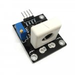
Found this current sensor with analog or digital output, 14U$. Once my amp pcb is completed, I'll order a pair to try. Seem to be the easier/cheaper solution to implement the current sensing. Thanks Paradod4 for the link.
WCS1800 Hall Current Sensor 35A Short Circuit / Overcurrent Aegis Module 700621733744 | eBay
WCS1800 Hall Current Sensor 35A Short Circuit / Overcurrent Aegis Module 700621733744 | eBay
Attachments
- Home
- Amplifiers
- Solid State
- Dartzeel amp schematic - build this?