You have a scope? I would be surprised if it didn't show some crossover distortion, giving the low bias
I ordered raw PCB from China 2 months ago. Much better layout PCB. But they can not go to their store. Yesterday they told me it will take another month or two. I want to build a new one with selected components. With two sets off outputs. I have ordered output devices. Price is same as hole module. I have a lot off 5401 and 5551 which I measure and select. I hope I can Finnish it after summer.
5.7 v IT came with 0.05 ohm resistors and seemed to oscillate ( multimeter only)
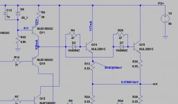
This is beginning to look very mysterious. So you have 5.7v/39R = 146mA through the drivers but only 9mA through the outputs? Impossible with the original resistor values. Please confirm the values of the base resistors for both drivers and outputs.
This is not the reason for the low bias but you should replace the output emitter resistors with the original 0.05ohm. These cannot be causing oscillations.
Is it possible to take a picture of the component side with sufficient resolution to read the resistor values?
Drivers base 21 ohm. Output base 47 ohm. Just measured them. I thought I had oscillating because of very running DC. So maybe no oscillating. Only confusing because of very very unstable DC.
Last edited:
There is some kind of issue with your board. Here is a sim with your current resistor values. The change from 27 to 47ohm does indeed reduce the current but not to the severe extent you observe. The voltage drop across the emitter resistors should be around 26mV
Attachments
Very strange I got some support from another guy on this forum, to change some resistors and it did not work at all. I will be back later. Now it is 2.22 AM I Copenhagen. Maybe I will change to 0.05 resistors later this day.There is some kind of issue with your board. Here is a sim with your current resistor values. The change from 27 to 47ohm does indeed reduce the current but not to the severe extent you observe. The voltage drop across the emitter resistors should be around 26mV
Very strange indeed, if it were me I would, print out the schematic, and one by one check values, and cross them off
Very strange indeed, if it were me I would, print out the schematic, and one by one check values, and cross them off
I will buy new PCB when available from a seller on eBay. Much better layout. I will build from zero. I have new output transistor coming soon also. And a lot off those small signal transistors at input. Seems like this is just to much trouble.
Drivers base 21 ohm. Output base 47 ohm. Just measured them. I thought I had oscillating because of very running DC. So maybe no oscillating. Only confusing because of very very unstable DC.
did you put the capacitor between R 9, R 10 and signal mass?
it is the 22 millifarad supercap
without this capacitor it is difficult to control the offset
it is a problem that can appear for the NON accurate selection of the various BJTs, a difficult selection because there is an NPN and PNP input, example.
Then there are drivers, pre drivers and MJL pair, a nice kasino
Last edited:
Yes it is there. When I build my own I will select the transistors. This I bought from Queenway store on Aliexpress. I will not use them again.
Last edited:
the 458 seems less demanding, like balance and stability.
There remains that accident of a signal ground supercapacitor that bypasses itself
you always need the control circuit of the DC offset up to 200 millivolts and that works together with the anti bump
There remains that accident of a signal ground supercapacitor that bypasses itself
you always need the control circuit of the DC offset up to 200 millivolts and that works together with the anti bump
I have designed the PCB of the 458 also with the stabilized power supply of IN, pre driver, driver and power amplifiers and stabilizer, if anyone is interested. You just have to make PCBs that cost very little
we are designing the PCB for the input and output offset control circuit and that works with the anti-dumping. In short, before switching on, check if there is an offset greater than 150 millivolts: if it is absent or lower, it activates the antibump
Calling the result of pure speculation a "458" is a bit extreme, isn't it? Or am i missing something?
I do not know.Calling the result of pure speculation a "458" is a bit extreme, isn't it? Or am i missing something?
I'm just saying that the scheme of 108, which I redone and modified, is very unstable and with big limitations
- unstable due to offset and in fact the supercap was designed later
- limitations due to its own pattern which has positive sides to listening as different negatives
- then the input capacitor is, in my opinion, a joke, but it takes, the only pair of finals that give what they can.
The 458, on the other hand, looks like an adult
- no input capacitor
- resistances on emitters
- UNFORTUNATELY all offset control is the work of the 2 capacitors from ENNE millifarad.
However, if you like an open loop scheme, either 108 or 458, at least that I know of.
As a fixed or preferred power amplifier or diagram, I have a different thing, much less critical and TOUT DC, all stabilized also in the final power section and, to finish, in a single frame, in short, an integrated, but with all-fet line stage.
External transformers in Faraday cage
External transformers in Faraday cage
The 458, on the other hand, looks like an adult
- no input capacitor
- resistances on emitters
- UNFORTUNATELY all offset control is the work of the 2 capacitors from ENNE millifarad.
However, if you like an open loop scheme, either 108 or 458, at least that I know of.
Only there is no publicly known circuit for the 458, it is just pure Hungarian fantasy 🙂 Not saying it is a bad amp, not at all, but it most probably bears no particular resemblance to the 458.
- Home
- Amplifiers
- Solid State
- Dartzeel amp schematic - build this?