What is the rating of resistance R23, R24 to choose 15 or 20 ohms when the amplifier is powered by 46 volts, to increase the quiescent current?:смущенный:
Thank you for sharing your interesting circuit and write up.
These however don't explain how you managed to get such a low distortion. I realise you never mentioned the power or load, so perhaps it is just 1W/8ohms but 0.03% thd is still a remarkably good result.
Yes you are right. Distortion of 0.03 percent is due to my output stage. The output stage in the original circuit provides 0.12% distortion and a fairly impressive range of high harmonics. So far, I'm in no hurry to share the output stage circuit in the public domain. But I can say that it is parallel on two pairs of output transitors, with modified current sources and positive power feedback to correct the minimum distortion at the first watt.
Ok guys, you all moved me.
I ordered 3 couples of the 108 pcb on Aliexpress; on eBay they do not list them, not even on demand. I want to try the two mods that are on 3SSS scheme and apply Domenico's suggestion about 2N5xxx:
- the Baxandall mod on Q5/7 and Q6/8 and moving the comp. capacitor;
- to lift from GND the common point of the two 12KOhms resistors;
- use the transistors array MMDT5451-7-F.
These mods are simple and should be reliable.
I will study on the "passive servo" whose starting point I posted in #1431.
The bad is that I have to wait until the half of October.
great, it will be interesting to know your opinion!
a 24 kΩ resistor must be of high quality and with a power of at least 3 W
I completely agree with Hattori, agree to raise the quiescent current of the output transistors. Domenico do your boards have 2 grounds? I do not think these will be better.😉🙂
my PCBs are purchased on Alipress or Aliexpress, in short, we understand each other.
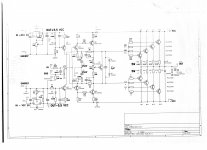
Then, in a frenzy, I developed it with 4 output pairs, changed the polarizations, of course, resistors on the emitters, VCC stabilization for the input BJTs with LM 317 instead of the zener, stabilized power supply for the driver and final stage, diodes fast recovery on lines and exits, another final than 108, but always a mess to check the offset without the supercap , this scheme
Attachments
But I can say that it is parallel on two pairs of output transitors, with modified current sources and positive power feedback to correct the minimum distortion at the first watt.
In other words: pure BS 🙄
< I will study on the "passive servo" whose starting point I posted in #1431. >
...........................
😡
A passive servo, not a guilty one! No power supply from 78/79xx most hated by most of the audiophile. Not any op-amp. No... nothing bad! a serie of two very long time constant with the right cut and Q, with the best quality components, as good to let pass only very subsounds an DC. To be studied on. I have not the solution yet. But the idea should be a good one.
Why 😡?
Last edited:
< No power supply from 78/79xx most hated by most of the audiophile > ...............
and why on earth? the audiophiles are perhaps all technicians of world value ............?
of 78 and 79 you have to see the cap on the way out, that's enough.
Better a shunt?
mmmmmmmhhh
and why on earth? the audiophiles are perhaps all technicians of world value ............?
of 78 and 79 you have to see the cap on the way out, that's enough.
Better a shunt?
mmmmmmmhhh
< A passive servo, not a guilty one! >
Okay
we make it faster:
who has tried to compare servo / cap and, if possible without cap and without servo?
If you need something to check the offset because the scheme just does not allow you to control it except to resort to caps and servos, you can always try, TO UNDERSTAND, the damage that the servo and the cap causes, checking the output offset with a tester . Of course, these are only experiments to be done carefully, but they serve to understand.
Once this is done, one wonders if it is worth going crazy with some schemes rather than looking beyond and looking for a scheme that does not have compensations, limitations and the need for various caps and servants.
I ordered 3 couples of the 108 pcb on Aliexpress;
These?:
2PCS Direct dartzeel NHB 108 15W*2 power amplifier board|Amplifier| - AliExpress
Last edited:
The cap solution just dont Work at all. Not for me I had to mount a DC solution in series with output -a relay.
Last edited:
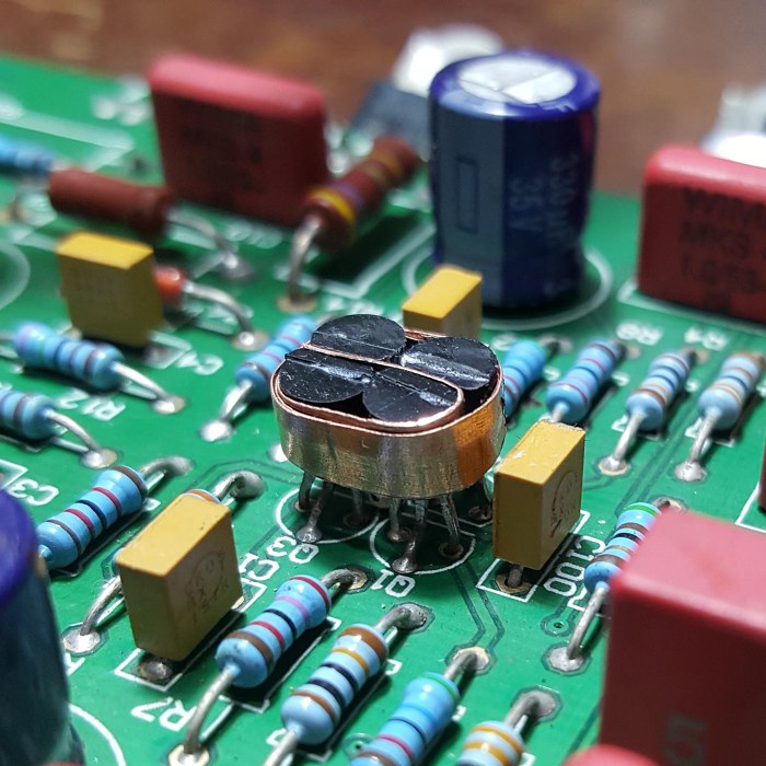
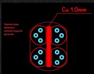
I'm just watching from a distance, but isn't the DC offset a thermal issue as the junction temperature fluctuates so does the offset, right? I'm think that part of the solution is to thermally couple the semiconductors with a smaller slab of copper and keep them warm/hot deliberately so that the junction temperature does not fluctuate with load.
A huge slab of heat-sink just makes the thermal difference bigger between the semiconductors. It's need so the temperature doesn't run away, but nothing is said about running hot at 85C (185F). Any thoughts?
A huge slab of heat-sink just makes the thermal difference bigger between the semiconductors. It's need so the temperature doesn't run away, but nothing is said about running hot at 85C (185F). Any thoughts?
On a different note: I'm looking at MJL4302AG/MJL4281AG and wondering what does the G stand for? Anyone tried them in DIY NHB 108 ?
Erlend, You have PM 🙂
all the problems related to the BJTs of the final stage and various differences that in a scheme like the 108 with a single pair are very important can be solved with the automatic closed-circuit bias that obviates the problems of the BJTs of a closed open loop, bjt PNP and NPN , chips like 1166
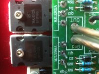
I found this russian build thread ????????? Dartzeel NHB-108 (????????? ?????, ?????? ????????? ? ????) [2] - ??????????? iXBT.com
Looks like they have been looking at thermally coupling things as well.
Looks like they have been looking at thermally coupling things as well.
certainly, it's great.
Strange that both on Dartzeel and on many other power amplifiers / preamps this excellent practice has long been ignored.
They rely on capacitors.
So better the matched dual chip
Strange that both on Dartzeel and on many other power amplifiers / preamps this excellent practice has long been ignored.
They rely on capacitors.
So better the matched dual chip
Dear piotrkundu, you did not read this forum well, I have long shared this photo and others, how to reduce the constant drift at the output without a super-duper capacitor. My amplifier is built just on such transistors, I will not say anything bad about them, the letter G means lead-free technology manufacturing.
Attachments
Thanks @paroxod4. I've been away for a while, so I haven't read all the posts. Are you the guy behind IGOR-81 ?
- Home
- Amplifiers
- Solid State
- Dartzeel amp schematic - build this?