Which design?
I still did not buy a MB yet because the discussions of the different designs are all over the place and I am not an experienced builder, so I can only build a design that will truly work.
The "Hungarian" 458 more or less fizzled, right? It did not sound good?
Is an "original" NHB 108 MB with the "3SSS" modification THE thing to do now? 1 pair or 2 or 3 pairs of output transistors?
Or is the NHB 108 just an overpriced, bad design not worth pursuing?
This is quite impressive if at full power. Even in class A with triple parallel outputs this is an incredible achievement for powers above 10W into 4ohms.
I still did not buy a MB yet because the discussions of the different designs are all over the place and I am not an experienced builder, so I can only build a design that will truly work.
The "Hungarian" 458 more or less fizzled, right? It did not sound good?
Is an "original" NHB 108 MB with the "3SSS" modification THE thing to do now? 1 pair or 2 or 3 pairs of output transistors?
Or is the NHB 108 just an overpriced, bad design not worth pursuing?
Last edited:
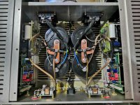
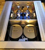
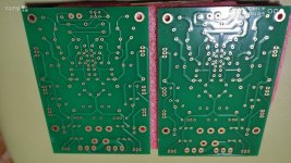
The circuitry of this amplifier is simple, but with a taste for music. I personally like the voltage amplifier, it has a good load capacity with current feedback. Its output works in class A, at a load of 10 kΩ we have 0.001 percent distortion with a short spectrum of higher harmonics. But there is also a construct, in dartzeel it is great, the signal path is short, the transistors on the heat sink are very literally located, and the design of the printed circuit board itself is excellent. The use of two, three or more pairs of transistors in the output stage has its own characteristics. It uses a well-sounding parallel output stage in class AB on one pair. The disadvantage is current sources, which, nevertheless, limit the potential of the output transitors and introduce their non-linearity. My opinion is that with this class AB topology, it is not allowed to use more than two pairs, because the effect of some sound blurring occurs. If you use a larger number of pairs of output transitors, then only in class A, where there is no current deviation as in AB. Separate power supply also has a positive effect: the voltage boost for the voltage amplifier is 60-70 volts, and for the output stage, due to the high reliability, 50-55 volts. Try this modification of the voltage amplifier that I suggested, my microdynamics in the sound immediately improved. And of course it's up to you to decide, after all the improvements, the amplifier sounds great for me. Here is one of the last cars I put together for a friend. It's a pity that there is no way to compare my version with the original, but I think the chances of the original will be small 😀
Attachments
Last edited:
Looking Good! 🙂
Are you using standard Chinese NHB-108 boards that you modified?
Could you, please, highlight the extra components/modification in your modified schematic?
I have (three) 500W 42+42VAC toroidal transformers and 2X rectifier boards each with 6X10.000 uF 80V for approx +- 59VDC.
Would that voltage work with your modification?
Last edited:
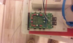
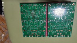
I used Chinese boards with a thickness of 2.4 mm I indicated the refinement of the voltage amplifier in post 1500, this revision can be used with the original output stage, the correspondence of the elements will have to be solved in a logical way)
I still did not buy a MB yet because the discussions of the different designs are all over the place and I am not an experienced builder, so I can only build a design that will truly work.
The "Hungarian" 458 more or less fizzled, right? It did not sound good?
Is an "original" NHB 108 MB with the "3SSS" modification THE thing to do now? 1 pair or 2 or 3 pairs of output transistors?
Or is the NHB 108 just an overpriced, bad design not worth pursuing?
mmmmh ......
if you want to get the clone of 108 you take the 2 cards on Alipress.
you place 2 transformers of maximum 300 VA and a pair of can caps x channel and everything works.
Maybe you need to add the supercap.
For the can caps go to your taste, but the DNA of the 108 project still remains.
The DNA of 108 I have already described, as far as my opinion is worth.
If you are not an expert, and this time NOT in my opinion, do not look for oddities like Hungarian or strange satellites on the net, but buy the Chinese clone
I used Chinese boards with a thickness of 2.4 mm I indicated the refinement of the voltage amplifier in post 1500, this revision can be used with the original output stage, the correspondence of the elements will have to be solved in a logical way)
Still confused, but a a higher level 🙂
In your post 1500 the picture of the board shows NO transistor at Q5 and a wire from the R5 to transistor Q7. There seems to be a a Capacitor? by Q7 as well? Is the Q5 underneath the board?
I will not go deep into the theory, my opinion is that first of all it is necessary to increase the signal transmission speed in the voltage amplifier. To do this, you can use a simple modification right on the board itself. I used 2sa1208 2sc2910 (Q5, Q6) transistors. Even leaving the output stage the same, this refinement improves the sound quality in this amplifier.
Your mod is to be tried! You connected Q5/Q7 and Q6/Q8 as Baxandall couples. Super easy to do in the board. I see you lifted from GND the common point of the two 12K resistors using a 24K one, like I said in my #1497. Any collateral (oscillation or instability)?
IMO, the original schema does not allow more than one output couple being useless adding others, the driving current is however limited by the two CCS.
My goal was to achieve at least 200W but I would have added the output NSCB stage even with a 100W goal, obtaining to move a lot higher the current limitation imposed by the two CCS, a Class-A driver, and non switching class-B output stage capable of very high current.
Confusing thread
I appreciate your advice.
It is just that so many people here are saying the original (cloned) 108 does not sound very good so I am just trying to find a simple modification that I can try on a standard card.
While one person swears by Supercapacitors, another prefers the Servo, yet others say you need Two pairs of output transistors to get good bass, and so on.
Some do not consider this amp to be a high end amp.
Sometimes this thread is very confusing.
mains.
The DNA of 108 I have already described, as far as my opinion is worth.
If you are not an expert, and this time NOT in my opinion, do not look for oddities like Hungarian or strange satellites on the net, but buy the Chinese clone
I appreciate your advice.
It is just that so many people here are saying the original (cloned) 108 does not sound very good so I am just trying to find a simple modification that I can try on a standard card.
While one person swears by Supercapacitors, another prefers the Servo, yet others say you need Two pairs of output transistors to get good bass, and so on.
Some do not consider this amp to be a high end amp.
Sometimes this thread is very confusing.
Last edited:
Then ,
- the servo is a disaster / disaster for any amplifier, always; yes, reset the offset, but at what price? Limit bass, mid-bass, dynamics, articulation, side scene and depth, it always happens like this.
- the cell / filter caps: if you want to clone as similar as possible, buy the Vishay cans, which are the same caps mounted on the original, BC 63 volt / 22,000 micro series
- the supercap is another sonic fetenzia, but it serves to reset the offset, to make the final safe and to protect the speakers from excessive offset and I consider it indispensable; clear that 22 MILLIFARAD, not MICROFARAD, that is, a capacity of a size greater than the BC which are from 22,000 micro, in that case, well, it is a technical nonsense, born for other uses, but used in 108 with an intervention by novice self-builder.
These are the things to do if you want to do 108 well, if you like it.
If you are looking for another sound there are other schemes that sound very different.
PS
The BC caps I would buy them from 22,000 / 100 Volts, not 63 Volts.
I would try some little bypass on the supercap, nothing else
Then ,
- the servo is a disaster / disaster for any amplifier, always; yes, reset the offset, but at what price? Limit bass, mid-bass, dynamics, articulation, side scene and depth, it always happens like this.
- the cell / filter caps: if you want to clone as similar as possible, buy the Vishay cans, which are the same caps mounted on the original, BC 63 volt / 22,000 micro series
- the supercap is another sonic fetenzia,
Had to google "fetenzia" 🙂 but agree wholeheartedly with all your points.
Probably not the best place for such a discussion, but what makes most servos suck?
Poorly chosen timeconstants? Poor isolation of out of band frequencies at output?
One can obviously design an electro-mechanical servo in which the offset is adjusted by a motor driven potentiometer and the motor is controlled by either an analogue or a digital control circuit. Such a servo should not have any sonic imprint as it just automates the process of adjusting by hand.
So, how do we improve the servo without involving early 20th century technology? What about a slow integrator followed by a slow optocoupler? I have seen discrete servos but i don't think i have ever seen something similar. The voltage drop across the photoresistor part is very small, so something proven to sound good like the Silonex part can be used.
my microdynamics in the sound immediately improved.
Thank you for sharing your interesting circuit and write up.
These however don't explain how you managed to get such a low distortion. I realise you never mentioned the power or load, so perhaps it is just 1W/8ohms but 0.03% thd is still a remarkably good result.
@ANALOG_SA
great !
And instead choose a stable circuit and without any need for supercaps, servos, input caps, compensations etc etc and limitations?
Of course, it is counter-reacted, but balancing the pros and cons of both I do not hesitate to choose the second scheme, which I have already posted.
In this diagram we can also speak of very modern and very stable current generators with LT 3092 type chips, of automatic polarizations that obviate the selection of the amps and that cancel the gap between PNP and NPN, not bad.
PS
fetenzia = nonsense = idiocy = absurd
Last edited:
mmmmh ......
if you want to get the clone of 108 you take the 2 cards on Alipress.
There are quite a few different NHB-108 card variants on Ali Express:
1 Real clone with One pair of power transistors
2 Real clone with One pair of power transistors and Supercapacitor
3 Real clone with Two pairs of power transistors
4 Real clone with Three pairs of power transistors And Servo
5 Original circuit but modified card layout and Speaker Protection and One pair of output transistors
6 Original circuit but modified card layout and Speaker Protection and Two pairs of output transistors
Most can be bought as kits or readybuilt or as only boards.
There may be more..
without Supercap
I would ignore the others, 2 couples, 3 couples, servant ................ etc
as always excellent speaker protection the series fuse the output:
ALWAYS protects you from trouble and shorts or something and I challenge anyone to distinguish whether or not there is
I would ignore the others, 2 couples, 3 couples, servant ................ etc
as always excellent speaker protection the series fuse the output:
ALWAYS protects you from trouble and shorts or something and I challenge anyone to distinguish whether or not there is
Last edited:
There are quite a few different NHB-108 card variants on Ali Express:
1 Real clone with One pair of power transistors
2 Real clone with One pair of power transistors and Supercapacitor
3 Real clone with Two pairs of power transistors
4 Real clone with Three pairs of power transistors And Servo
5 Original circuit but modified card layout and Speaker Protection and One pair of output transistors
6 Original circuit but modified card layout and Speaker Protection and Two pairs of output transistors
Most can be bought as kits or readybuilt or as only boards.
There may be more..
The solutions with two or more couples deny the designer's proposal about the absence of Re, I wouldn't go for them. I would choose the bare single pair pcb and buy good quality components by yourself.
Unless you want to experiment another way to use multiple output pairs: you must increase the two CCS's current to 250mA at least (now they deliver abouyt 120mA) verifying to remaining inside the SOA of the MJE1503x, also you must take care of the increased heat (a lot more) and have a very special care in matching all the output couples in order to avoid the Re. Too busy for us being "researchers", not a factory with a wide budget.
Remember to short all the throughpads, do not rely on their hole metallization.
Ok guys, you all moved me.
I ordered 3 couples of the 108 pcb on Aliexpress; on eBay they do not list them, not even on demand. I want to try the two mods that are on 3SSS scheme and apply Domenico's suggestion about 2N5xxx:
- the Baxandall mod on Q5/7 and Q6/8 and moving the comp. capacitor;
- to lift from GND the common point of the two 12KOhms resistors;
- use the transistors array MMDT5451-7-F.
These mods are simple and should be reliable.
I will study on the "passive servo" whose starting point I posted in #1431.
The bad is that I have to wait until the half of October.
< I will study on the "passive servo" whose starting point I posted in #1431. >
...........................
😡
...........................
😡
I completely agree with Hattori, agree to raise the quiescent current of the output transistors. Domenico do your boards have 2 grounds? I do not think these will be better.😉🙂
Last edited:
- Home
- Amplifiers
- Solid State
- Dartzeel amp schematic - build this?