sorry, but I just can't understand why you don't use SMD chips with the 2 PNP or NPN BJTs or with the industrially matched BJTs - NPN and PNP:
you avoid a lot of problems, see, for example, the FMBM 5551 and FMBM 5401 where the 2 bjt are indistinguishable, in the test
Thanks a lot for the information. I didn't know those chips existed.
I see now. DMMT 5551 and DMMT 5401 but how matching booth?
What if they also have different hFEs?
I see now. DMMT 5551 and DMMT 5401 but how matching booth?
What if they also have different hFEs?
Last edited:
Great, just no one mentioned it before !
How many should I buy if they were paired with each other so that all 4 transistors are paired ?
How many should I buy if they were paired with each other so that all 4 transistors are paired ?
sorry, but I just can't understand why you don't use SMD chips with the 2 PNP or NPN BJTs or with the industrially matched BJTs - NPN and PNP:
you avoid a lot of problems, see, for example, the FMBM 5551 and FMBM 5401 where the 2 bjt are indistinguishable, in the test
Never heard of them.
these are statements that, without knowing what one is talking about, that is, without seeing the patterns, appear quite superficial
Not sure what you mean. Does Google call the circuit "pattern" ? Easy to find what Cubie 2 looks like. And does it matter? It is just a subjective comparison between a standard capacitance multiplier and simple RC filtering.
My point is that the preference one way or the other is entirely subjective and a question of taste. Makes no sense to insist that one is better than the other.
Attachments

Great, just no one mentioned it before !
How many should I buy if they were paired with each other so that all 4 transistors are paired ?
mmmmh ...... being the dual chips, the two bjt, PNP and NPN, should be best matched, I don't think they are dual chip not matched. We consider computerized production by multinationals and not selection by hiend phenomena
Not sure what you mean. Does Google call the circuit "pattern" ? Easy to find what Cubie 2 looks like. And does it matter? It is just a subjective comparison between a standard capacitance multiplier and simple RC filtering.
My point is that the preference one way or the other is entirely subjective and a question of taste. Makes no sense to insist that one is better than the other.
I do not insist, everyone does their own convenience, I only expose my opinion, but when I read about the usual veil that disappears, well, defining this diction superficial is very diplomatic
Martin Colloms has reviewed the 108 Model 2 and there are some measurements. Distortion appears much lower than anticipated which means that our attempt to recreate a Model 2 based on the well known schematic glimpsed on Herve's screen and drawn by Shany is defective.
Which perhaps should have been obvious as there is just not enough current gain not to overload the voltage gain stage. Of course this is most severe at low impedance loads. My speakers drop down to 2.5ohms which times x100 for the output transistors Hfe means 250ohm load at the VAS (acronym used loosely). Clearly low distortion will be impossible without a darlington connection at output.
Not sure why it took me so long to realise something so simple. No excuse really.
On the bright side, adding two more transistors reduces the distortion 3-4 fold. The question is are these extra transistors present in the original?
I repeat, I bought the 108 or clone, heard and worked around it a lot.
In the end the scheme was no longer the one known or believed to be the 108, but another and the sound as well. The DNA remains, but we can no longer talk about 108 Dartzeels, and this without discussing what sounds best, is another power amp ........... stabilized power for inputs, drivers and amps, 4 pairs of final with ERRE on the emitters, polarizations changed, changed the input cap.
I could do it all again, I would only change the entry cap, too much work and use of materials (selection) to get to what!
If someone clones 108 means they like it, so why change it?
Domenico, this is about the 458 circuit, it is not a discussion of 108 model 1, but model 2 which is supposed to be a 458 with only two parallel outputs. Your version of the 458 circuit suffers the same fatal flaw.
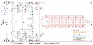
dartzeel sounds good, but due to the large distortion it is still unclear. To get rid of this turbidity and add "air", there it is necessary to modify the driver and apply an output stage with two pairs of output transistors, also without applying global feedback. In this case, it is necessary to avoid the use of current-equalizing resistors in emitters.
The signal flow rate in this circuit is of the order of 370ns, of which 350ns is a driver and 20ns is a parallel output stage. If we use a pair of Baxandal in the output stage of the driver, its speed will decrease from 350 to 90ns, which has a favorable effect on microdynamics.
The signal flow rate in this circuit is of the order of 370ns, of which 350ns is a driver and 20ns is a parallel output stage. If we use a pair of Baxandal in the output stage of the driver, its speed will decrease from 350 to 90ns, which has a favorable effect on microdynamics.
Last edited:
Domenico, this is about the 458 circuit, it is not a discussion of 108 model 1, but model 2 which is supposed to be a 458 with only two parallel outputs. Your version of the 458 circuit suffers the same fatal flaw.
True, in fact my favorite ending is another one, indeed it is an integrated with line
dartzeel sounds good, but due to the large distortion it is still unclear. To get rid of this turbidity and add "air", there it is necessary to modify the driver and apply an output stage with two pairs of output transistors, also without applying global feedback. In this case, it is necessary to avoid the use of current-equalizing resistors in emitters.
The signal flow rate in this circuit is of the order of 370ns, of which 350ns is a driver and 20ns is a parallel output stage. If we use a pair of Baxandal in the output stage of the driver, its speed will decrease from 350 to 90ns, which has a favorable effect on microdynamics.
I think that the 108, because I am talking about this because I listened to and cloned this, the original / true one ............... I am not talking about the preamp which I think is <terrible>! both an ending that is talked about ONLY for the cost it requires respect, but certainly not for how it sounds.
Minimum dynamics, dark, does not descend, has no articulation on the bass and the medium bass is very questionable.
IN MY OPINION .
So those 2 transformers of 1000VA each and those 132,000 micro channels for a pair of power amplifiers, what are they for?
No wonder it sounds dark between Wima inbound and supercap.
However I admit that the voices are fascinating and with a very pleasant note of warmth and pleasantness, but it is a little bit for € 38,000 and also for € 3,800, always in my opinion
Then you have to understand what you are comparing it with and what you are looking for, but never believe that it sounds like a 300 B, NO!
I've been messing around with this amplifier for several years and I have learned this circuitry well. As a result, in order for this device to fully sound, I applied my own output stage, and the voltage amplifier was also slightly modified, as a result I got 0.03 percent distortion without a global negative connection. And now this beast really sounds good. 🙂
I applied my own output stage, and the voltage amplifier was also slightly modified, as a result I got 0.03 percent distortion without a global negative connection. And now this beast really sounds good. 🙂
This is quite impressive if at full power. Even in class A with triple parallel outputs this is an incredible achievement for powers above 10W into 4ohms.
The voltage amplifier has a very low distortion on its own, not much to be gained there.
I've been messing around with this amplifier for several years and I have learned this circuitry well. As a result, in order for this device to fully sound, I applied my own output stage, and the voltage amplifier was also slightly modified, as a result I got 0.03 percent distortion without a global negative connection. And now this beast really sounds good. 🙂
We were discussing philosophy going far away from the subject, overall because of my fault: everything is knowledge exchange, and Domenico and Analog_sa are always interesting to be heard. But your post takes us back to the topic of this forum. I posted my mod at #1267, would you please like to share yours? Did you try to lift from the ground the common point of emitter resistors (12KOhm) on the first MJ1503x?
We were discussing philosophy going far away from the subject, overall because of my fault: everything is knowledge exchange, and Domenico and Analog_sa are always interesting to be heard. But your post takes us back to the topic of this forum. I posted my mod at #1267, would you please like to share yours? Did you try to lift from the ground the common point of emitter resistors (12KOhm) on the first MJ1503x?
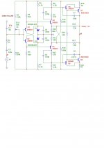
I will not go deep into the theory, my opinion is that first of all it is necessary to increase the signal transmission speed in the voltage amplifier. To do this, you can use a simple modification right on the board itself. I used 2sa1208 2sc2910 (Q5, Q6) transistors. Even leaving the output stage the same, this refinement improves the sound quality in this amplifier.
Attachments
Last edited:
- Home
- Amplifiers
- Solid State
- Dartzeel amp schematic - build this?