Yes, our home is split 2 phase (center tapped) with each 115vac phase out by 180 degrees. You can connect across 2 AC socket lives to get your 230vac
No luck! All outlets close or not that far from the audio-set are on the same phase. I could find only one with reverse phase but it is too far. I must keep that chinese crap.
I would suggest this cabling schema. The only common point point between the two channels is after the ground coupler.
It is intended to be a physical schema, do not move any joint.
With this cabling, I never had hum problems.
Yes I have done like that often. In this I use two transformers. Sometimes I order transformers with 4 x 50 vac. I will do exactly what I do in those. All four midpoint cables to same connection on Gnd capacitor supply.
That's correct. So the problem is elsewhere.
It is the first amplifier I build that has the problem of loud hum with input left open.
I'm sure you did. However, the question is: did you short the input or connect any good source to it? Are you sure that the metal of the pin jack is really insulated from the panel?
It is the first amplifier I build that has the problem of loud hum with input left open.
I'm sure you did. However, the question is: did you short the input or connect any good source to it? Are you sure that the metal of the pin jack is really insulated from the panel?
I need another couple of pcb to use better quality components, to try to improve the main circuitry and to get rid of the mid-point servo board. Here are some more mods to be experimented, the schema and the values are a starting point. I think I'll buy pcbs on Aliexpress.
Any comments will be appreciated.
it depends on what you want to do and how.
IF you want the Dartzeel or 108 clone you can take the Chinese cards from Alipress and add the 22 MILLIFARAD supercap to check the offset, plug in the power and walk.
If instead you want - INVENT - or try to improve (offset control!!) The Chinese board you can intervene:
- entry cap (the Wima is dark, rumbling and very slow), there is much better
- the first 4 TO 92, 2N 5551 and 2N 5401 which must be almost perfect as a selection, which the Chinese card ignores. Now you have two options, either you select 2N, or you go for excellent chips, like
EMZ1 FHA, which have bjt PNP and NPN industrially matched, OR you buy FMBM5551 and FMBM5401 and cross the bjt. So either you remake the PCB or try to intervene on the Chinese PCB, but only if you have manual skills.
PS / NB
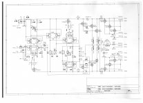
the scheme you posted appears to be a scramble of 108 and not too well done
That's correct. So the problem is elsewhere.
It is the first amplifier I build that has the problem of loud hum with input left open.
I'm sure you did. However, the question is: did you short the input or connect any good source to it? Are you sure that the metal of the pin jack is really insulated from the panel?
The back plate is not metal but 12 mm thick pertinax. Shorted inputs ( 75 ohm) results in no hum. But problems is maybe the transformer at the output of my PS Audio dac. They have caused problems with an other amplifier. I will try with a buffer in between.
That's correct. So the problem is elsewhere.
It is the first amplifier I build that has the problem of loud hum with input left open.
I'm sure you did. However, the question is: did you short the input or connect any good source to it? Are you sure that the metal of the pin jack is really insulated from the panel?
It's insulated from panel as panel is not metal.
Do not forget, this amp has a much higher input impedance than most SS amps. With the input open more hum is unavoidable.
Yes off course but I have only 20 kohm across after the 51 ohm series resistor. I use a Muse 47 uf as input series capacitor.
Reduced input impedance less noise and hum I think. I will get the answer later today. Now the midpoint from both transformers is at the midpoint at the two capacitor pcb's.
it depends on what you want to do and how.
IF you want the Dartzeel or 108 clone you can take the Chinese cards from Alipress and add the 22 MILLIFARAD supercap to check the offset, plug in the power and walk.
If instead you want - INVENT - or try to improve (offset control!!) The Chinese board you can intervene:
- entry cap (the Wima is dark, rumbling and very slow), there is much better
- the first 4 TO 92, 2N 5551 and 2N 5401 which must be almost perfect as a selection, which the Chinese card ignores. Now you have two options, either you select 2N, or you go for excellent chips, like
EMZ1 FHA, which have bjt PNP and NPN industrially matched, OR you buy FMBM5551 and FMBM5401 and cross the bjt. So either you remake the PCB or try to intervene on the Chinese PCB, but only if you have manual skills.
PS / NB
the scheme you posted appears to be a scramble of 108 and not too well done
Dear Domenico,
any suggestion to improve my scheme will be well accepted. But you must be precise, saying "the scheme you posted appears to be a scramble of 108 and not too well done" is not any help for anybody here. I like to share my experience when it leads to an improvement, at least in my opinion; don't you? So, please, share your idea.
There are some targets I want to achieve: I have 2 transformers 50+50Vac 625VA and 1 transformer with a double 60+60Vac 1KVA that need to be used; at least 200Wrms of output power on 8Ohms; no global feedback.
Searching the net with these targets, I found this clone on eBay. But I'm married with my targets, not with this clone. Should I start from scratch, I would use the Aikido project as front-end/VAS and a triple darlington NSCB back end. But is is not that simple to design the servoes needed to control current drawing and midpoint, even worse (and dangerous) if you try to design with the cc coupling as a target. I'm not a factory!
Other than my ears, I have no instrumentation here, in Utah, where I moved; all my lab equipment is in Rome, where, for the foreseeable future, I have no way to go.
Coming back to our topic, during last days I came to the decision of drawing myself the pcb to use better quality components, that will be bigger. But I still need the chinese pcb to continue experiments before finalizing my design. I think I will use the transistor arrays you said (this is a good and precise suggestion but the EMZ1 FHA that is too low on breakdown voltage, good perhaps used in cascode). I have no idea where to buy MJE1503x matched transistors from, with confidence; the hfe of mine are quite different among NPN and PNP (this could be another good suggestion).
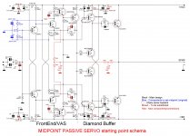
In my post #1377 I forgot to enclose the schema of a starting point solution of a passive servo (subsonic feedback) to try to trash the active servo, I'm posting it here. However I don't see that big problem with the chinese servo, at least not with my mod; I never tried the servo "original".
Attachments
Now my Dartzeel is wonderful. The first 10 minutes is terrible. Midpoints from both transformer to the midpoint between the two PCB for each channel.
Erlend Sæterdal,
Glad to know it finally works. However, your description is not that clear, could you post the schema of your cabling, like mine in #1415?
Glad to know it finally works. However, your description is not that clear, could you post the schema of your cabling, like mine in #1415?
Erlend Sæterdal,
Glad to know it finally works. However, your description is not that clear, could you post the schema of your cabling, like mine in #1415?
Almost like your but two transformers. Midpoint of both transformers too midpoint off the two capacitor PCB. In between the two PCB. Earlier there was two transformers and no connection between their Gnd.
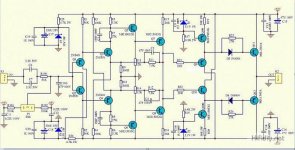
I think this is the pattern of 108, the pattern sold on Alipress from China
.
mmmmh ......
I think you know how 108 sounds, NOW, well. It is an open loop with only one pair of power amplifiers ... nothing to object, but the final performances can be predicted in percentage terms.
If you've listened to the original, you know what I'm talking about.
I have modified the Chinese card purchased from Alipress, perhaps modified too much to the point of being quite different, in terms of sound, from the original scheme.
That's why I mentioned what you want to do and what you want to achieve.
Then you mention to me wanting to use some transformers you find yourself, and then, okay, even if it seems to me <reductive>.
Attachments
Last edited:
the schematic I posted is not complete:
between R 9 / R 10 and mass there must be a cap, the supercap, of 22 MILLIFARAD, not MICROFARAD! ! ! , to check the offset and hope to cut with this high pass as low as possible, although it is always nonsense to cut
very low and hope you don't feel the cut.
For this scheme you can do a little without changing it:
- change the entry cap, a fetenzia like sound, MY OPINION, but aligned with Dartzeel thinking
- the 4 input BJTs to be replaced with a chip or two chips as I mentioned (if you are interested you can learn more) to try to better control the offset; if one really wants to select the 2Ns, audiophiles are closely linked to similar customs, at least place them attached to each other, 2 to 2
- the diode in series the final.
I add :
IN MY OPINION, but I bet because I tried, 2 transformers of 1.000VA and 12 filter caps of 22.000 / 63 volts are a NON sense: and to do what!
Have the bass? , but let's go.
They appear to be fillers to try to justify the final selling price
from 150 to 230 watts of power, all DC, very stable on any load, no compensation, very firm offset, fully stabilized both input stages, drivers and final power stages, a decent start, but .......... ..... upgradeable with
- switching power supply
- automatic control of the offset (balance the endings that happen to you, not caring about selecting them and you are sure that the polarization of the P and N will always be optimal
....................
do you think it's stuff?
- switching power supply
- automatic control of the offset (balance the endings that happen to you, not caring about selecting them and you are sure that the polarization of the P and N will always be optimal
....................
do you think it's stuff?
analog_sa, what are you doing here? Are you in love with this ugly design?
Yes and i fully acknowledge the ugliness. It fails miserably with my "difficult" speakers but fits the easy ones like a glove. 4 channels in passive biamping. It refuses to play loud and the bass is too soft and it's not suitable for rock but i still love it.
There is clearly some symbiosis with the speakers where the complementary ugliness of the two cancels out 😀
A friend with VOT A7 has a similar reaction, only he added output transformers. Or maybe autoformers.
- Home
- Amplifiers
- Solid State
- Dartzeel amp schematic - build this?