Hello Mr I,The case is recovered from a 800MHz RF link and is meant to be wall mounted.
I could've flipped the U channel brackets over so that the heatsink fins were vertical but couldn't be bothered in the end due to the size of the heatsink, and also focusing on other tasks.
I had a ferrite clamp on the rca input due to unshielded wires, and I was playing with a SDR (software defined radio) nearby. ferrites that size do nothing for audio.
That case is just fine, I use these polyester fiberglass reinforced cabinets on regular basis for industrial purposes, for process control. They provide excellent isolation even at higher voltages and are easy to work with. Also, there is enough room below the casing to allow for natural convection. With that heat sink you're on the safe side even on higher voltages. That's a good example of real world engineering, results with no big fuss.
I also have a pair of that version of the boards without a capacitor in the middle, above 5551, 5401, just in green color. I haven't noticed any difference.
Well done mate. 😎
Be carefull not to burn it all together at that voltage with a modest heat sink.With 2x59V I should get a case with larger heatsinks?

Building a clone of an expensive amplifier isn’t cheap at all, but it isn’t really expensive either. It just costs. Board and electronic components are just an initial cost, if you want to do it properly, otherwise you can end-up with an useless result and that’s what we don’t want.
I run a NHB-108 clone on about 56,5 V, using 500 VAC 40-0-40 thoroids and use 0,3 C/W heat sinks with external dimensions 200mmX300mmX40mm.
There is a certain amount of money you will have to spend on building of the chassis, and this will cost you a lot of time. Doing this should be pleasure, not the money or savings, otherwise it isn’t worth it. Life itself costs but it can be pleasure.
I have tested my clone at different voltages: 24V, 42V and 56,5V. The higher the voltage, the better sound quality. At 56,5 V heat sink was very warm, should I say about 50°C, I was able to touch the output transistors for a couple of seconds, not longer, but there was no sensation of burning. I was able to comfortably run the amplifier for hours, at constant, steady state I didn’t bother measuring temperature but intend to buy an IR thermometer to be sure my amplifier is running safely.
Heat sinks cost 43 EUR each, thoroids cost 60 EUR each, prices without VAT. Ad to this 10 or 20 for packaging and transportation. All together, this cocts 226 EUR +VAT.
There is no way around this.
Good luck with your project. 🙂
The higher the voltage, the better sound quality.
Interesting. I have two clones: one at 56v and a second @36v. They are not identical as resistor values in the lower rail amp have been adjusted to keep operating conditions similar. My low rail amp sounds significantly better but i think it is because of the different series Mundorf caps, better connectors, etc.
What is more interesting is that the original is supposed to work into lower impedance loads at severely reduced rail voltages, i believe no more than 30v, without any readjustment of bias. I wonder what owners think about this mode.
Ime the original single pair version is not well suited to sub 4-ohm or difficult speakers irrespective of supply voltage or power level. The sound is constricted and generally horrible.
Ah, I see now,Interesting. I have two clones: one at 56v and a second @36v. They are not identical as resistor values in the lower rail amp have been adjusted to keep operating conditions similar. My low rail amp sounds significantly better but i think it is because of the different series Mundorf caps, better connectors, etc.
What is more interesting is that the original is supposed to work into lower impedance loads at severely reduced rail voltages, i believe no more than 30v, without any readjustment of bias. I wonder what owners think about this mode.
Ime the original single pair version is not well suited to sub 4-ohm or difficult speakers irrespective of supply voltage or power level. The sound is constricted and generally horrible.
For initial testing I usually use a spare power supply with 50V rated capacitors to minimize collateral damage if anything goes wrong. For 56.5V test I have used another board stuffed with 100V rated capacitors and larger 25 amp rectifiers. This sideshow change has made the most significant contribution to the sound quality.
Thanks.
By the way, from your recent discussion with our colleague Domenico I conclude, please correct me if I am wrong, that there is another way to further increase sound quality by removing toroids from the power amp chassis. In that case, it would be much more convenient to keep the entire power supply in one chassis and amplifier in another. I intend to build more amplifiers and modular approach to power supplies could prove incredibly convenient. Removing power supply from amplifier can improve routing of air flow and better routing of wiring inside amplifier.
This discussion has proven extremely useful and inspiring to me.
Muito obrigado! 😎
Last edited:
Be carefull not to burn it all together at that voltage with a modest heat sink.
I have tested my clone at different voltages: 24V, 42V and 56,5V. The higher the voltage, the better sound quality. At 56,5 V heat sink was very warm, should I say about 50°C, I was able to touch the output transistors for a couple of seconds, not longer, but there was no sensation of burning. I was able to comfortably run the amplifier for hours, at constant, steady state I didn’t bother measuring temperature but intend to buy an IR thermometer to be sure my amplifier is running safely.
I already purchased three! 500VA 2x42V toroidal transformers from a guy on ebay thinking I made a good deal.. I cannot return those. Are you saying I cannot use those?
I Think I read somewhere you can lower the current at higher voltages for less heat? What exactly happens when you lower the current? Will it run in class A to a lower output power and after that point run in class A/B, or what will happen?
Heat sinks cost 43 EUR each, thoroids cost 60 EUR each, prices without VAT. Ad to this 10 or 20 for packaging and transportation. All together, this cocts 226 EUR +VAT.
Where did you get your heatsinks?
Heatsinks-chassis
I was looking for the smallest possible design that will do the work of transferring the heat for many reasons, not just cost. The smaller the cooler 🙂
You mentioned a figure, 0.3, thanks!
The problem is that few, if any, suppliers give a number on the heat transfer efficiency of different chassis designs, that is why I am asking
I run a NHB-108 clone on about 56,5 V, using 500 VAC 40-0-40 thoroids and use 0,3 C/W heat sinks with external dimensions 200mmX300mmX40mm.
I was looking for the smallest possible design that will do the work of transferring the heat for many reasons, not just cost. The smaller the cooler 🙂
You mentioned a figure, 0.3, thanks!
The problem is that few, if any, suppliers give a number on the heat transfer efficiency of different chassis designs, that is why I am asking
I already purchased three! 500VA 2x42V toroidal transformers from a guy on ebay thinking I made a good deal.. I cannot return those. Are you saying I cannot use those?
No problem with your transformers provided you have ample heatsinking. The two output pairs should also resolve worries about 4ohm operation.
I already purchased three! 500VA 2x42V toroidal transformers from a guy on ebay thinking I made a good deal.. I cannot return those. Are you saying I cannot use those?
I Think I read somewhere you can lower the current at higher voltages for less heat? What exactly happens when you lower the current? Will it run in class A to a lower output power and after that point run in class A/B, or what will happen?
Where did you get your heatsinks?
I purchase from Reichelt, Germany. This the the link to the heat sink.
Security Check
The picture on that link can be unintentionally deceptive: the actual heat sink looks much wider and weights about 3,5kg each.
You can purchase it elsewhere. It is product of "Fisher Elektronik". Though, I suspect you wouldnt get beter pricing - Reichelt is really good.
Regarding the transformer voltage: mine are just 2V lower (40V). You will end-up a couple of volts below 60VDC depending on your mains voltage, so take care to have adequate capacitors and be careful, the amp will get hot.
Last edited:
By the way, from your recent discussion with our colleague Domenico
I neither agree nor disagree with Domenico. It is a compromise.
Getting the transformers away from active circuitry reduces electromagnetically induced noise and mechanical vibration. Otoh, the connecting wires to the transformers now have to carry a much higher current leading to thicker wires and more radiation. In my system PS wire is very audible and so are power connectors which now have to be rated for much higher current.
Looking at commercial high end power amps, the physical separation of transformers/power supply and active circuitry is as rare as the proverbial hen's teeth. Off the top of my head i only recall a Krell built this way, though there are certainly others. There must be reasons for this apart from cost.
-I neither agree nor disagree with Domenico. It is a compromise.
Getting the transformers away from active circuitry reduces electromagnetically induced noise and mechanical vibration. Otoh, the connecting wires to the transformers now have to carry a much higher current leading to thicker wires and more radiation. In my system PS wire is very audible and so are power connectors which now have to be rated for much higher current.
Looking at commercial high end power amps, the physical separation of transformers/power supply and active circuitry is as rare as the proverbial hen's teeth.
Off the top of my head i only recall a Krell built this way, though there are certainly others. There must be reasons for this apart from cost.
there are reasons, I think, of packaging and problems of possible errors of connections, if flying, by the customer, as well as costs.
it is undeniable that placing the transformers and bridges in another box is preferable because the transformer excels in vibrating and radiating.
In any case, the wiring between the external power supply and the chassis of the power amplifier can yes - act as an antenna -, but it can be shielded, the wiring is not a problem nor if through connectors (there are economic connections that have poles that support 30 A) and not even if in single cable from power supply to chassis of the power amplifier.
it is always a matter of choices and we, to earn those famous 6 db, have been forced to follow an alternative by anyone, or almost, never adopted, opening up finals of a certain power
" take care to have adequate capacitors and be careful, the amp will get hot.
I am planning to get 80V capacitors and also a Soft Start circuit with a 75 Centigrade cutoff:
Buy Products Online from China Wholesalers at Aliexpress.com
The NTC resistors softstart the current to the transformer/capacitors and then the second relay opens the current to full blast after 3 seconds. There are also two temperature sensors and you can start the circuit using a small DC switch on the front panel
If I can :
I would ONLY use 100 volt capacitors. Using 63 volt capacitors and feeding at 55 can stress the armor of a 63 volt capacitor more than a 100 volt capacitor.
I would ONLY use 100 volt capacitors. Using 63 volt capacitors and feeding at 55 can stress the armor of a 63 volt capacitor more than a 100 volt capacitor.
we, to earn those famous 6 db
But you can earn those famous 6db by repositioning and distancing the transformers if the chassis allow for that, can't you? Combined with building an enclosure around the transformer.
Having a switchable input impedance of 50ohms is also beneficial for reducing input induced noise.
The mechanical side, at least for me, is a lot more difficult to resolve.
Lo apprezzo caro Domenico 🙂-
there are reasons, I think, of packaging and problems of possible errors of connections, if flying, by the customer, as well as costs.
it is undeniable that placing the transformers and bridges in another box is preferable because the transformer excels in vibrating and radiating.
In any case, the wiring between the external power supply and the chassis of the power amplifier can yes - act as an antenna -, but it can be shielded, the wiring is not a problem nor if through connectors (there are economic connections that have poles that support 30 A) and not even if in single cable from power supply to chassis of the power amplifier.
it is always a matter of choices and we, to earn those famous 6 db, have been forced to follow an alternative by anyone, or almost, never adopted, opening up finals of a certain power
Does it help if I use short, shielded cables. A separate power supply is so valuable in case of multiple amplifiers and gives incredible freedom of choice of routing air flow within the amplifier. Right now I'm in the middle of making decisions on layout of two amplifiers I have completed recently.
Last edited:
it seems not very influential, but the layout, ok of the pCB, but also of the inside of a finale, is not immediate.
I am to position any filter capacitors close to the power amplifiers, as in the Spectral 260, for example, etc etc
The same condenser, even a very bad SNAPIN, placed close to the end or 10 or 15 centimeters away, provides different results.
-
example :
we the stabilizers of the power amplifiers are 5 millimeters away from the transistor they must supply.
Another example, if you want to put the transformer in the same chassis as the final PCB:
the IN and pre driver stage, we position it through elastic silent blocks with M 3, details, but which can make the difference, if added together.
Then you have to understand what you are looking fo
Last edited:
But you can earn those famous 6db by repositioning and distancing the transformers if the chassis allow for that, can't you? Combined with building an enclosure around the transformer.
Having a switchable input impedance of 50ohms is also beneficial for reducing input induced noise.
The mechanical side, at least for me, is a lot more difficult to resolve.
-
Yes, those 6 db can be searched otherwise, but the possible vibrations of the tarsformers remain.
However, as always, it is only a matter of choices.
We, with the scheme illustrated above, have tried to extremize it to get the best of it, even with special resistances that are very interesting.
Going back to 108, I agree that the entry stage is very critical, critical with relative impedances which, with BJTs, cannot be raised too much.
True, the mechanical part is hell and the heat sinks themselves cost madness: we assembled them with aluminum rectangles 40 x 80 x 2.
Going back to 108, I saw the scheme of the 408 and, IF REAL, it seems that even in Dartzeel they tried to bypass the problems of the entrance stage
Don't forget, you will have to fix your transistors to the heat sink with M3X10 screws and you have to make threaded boreholes on that heat sink. To do that you will need a 3mm drill bit and a set of screw taps (Ger.: Gewindebohrer) in accordance to the DIN 352. Making threads into aluminium can be a bit tricky because ordinarry screw taps easily get stuck in aluminium and then breaks. With DIN 352 taps you do that in three consecutive steps. Look here: YouTube.I am planning to get 80V capacitors and also a Soft Start circuit with a 75 Centigrade cutoff:
Buy Products Online from China Wholesalers at Aliexpress.com
The NTC resistors softstart the current to the transformer/capacitors and then the second relay opens the current to full blast after 3 seconds. There are also two temperature sensors and you can start the circuit using a small DC switch on the front panel
You can find a set of DIN 352 taps anywhere, in a store like Wallmart.
Also, you will need mica tags and thermal paste to do this task properly. And do this carefully because thermal characteristics of your amplifier will depend on this.
Good luck.
Here is a link to s similar but M4 set of screw taps.
TERRAX by RUKO Handgewindbohrer Satz DIN 352 Geschliffen M4: Amazon.de: Baumarkt
Last edited:
Heatsink/amplifier subassembly
I was thinking of using 8 or 10mm thick aluminium bars, approx. 150 by 80 mm to do the 3 mm threads and then attach the amplifier/power transistors to the aluminium bar using the 3 mm screws and then attach the whole aluminum bars/amplifier subassembly with screws/nuts going through the large heatsinks of the chassis, using heatsink paste . That way I will not risk "ruining" the large heatsink and I can reuse the heatsinks/case should I not like this particular amp.
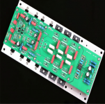
Use a large aluminium bar in a fashion similar to the one this card is attached to:
Don't forget, you will have to fix your transistors to the heat sink with M3X10 screws and you have to make threaded boreholes on that heat sink. To do that you will need a 3mm drill bit and a set of screw taps (Ger.: Gewindebohrer) in accordance to the DIN 352. Making threads into aluminium can be a bit tricky because ordinarry screw taps easily get stuck in aluminium and then breaks. With DIN 352 taps you do that in three consecutive steps. Look here: YouTube.
You can find a set of DIN 352 taps anywhere, in a store like Wallmart.
Also, you will need mica tags and thermal paste to do this task properly. And do this carefully because thermal characteristics of your amplifier will depend on this.
Good luck.
I was thinking of using 8 or 10mm thick aluminium bars, approx. 150 by 80 mm to do the 3 mm threads and then attach the amplifier/power transistors to the aluminium bar using the 3 mm screws and then attach the whole aluminum bars/amplifier subassembly with screws/nuts going through the large heatsinks of the chassis, using heatsink paste . That way I will not risk "ruining" the large heatsink and I can reuse the heatsinks/case should I not like this particular amp.
Use a large aluminium bar in a fashion similar to the one this card is attached to:
Attachments
Last edited:
To do that you will need a 3mm drill bit
If you need to tap for 3mm you should drill with 2.5mm.
I was thinking of using 8 or 10mm thick aluminium bars
An excellent idea. Being lazy i ended up having lots of heatsinks that look like swiss cheese 😀
- Home
- Amplifiers
- Solid State
- Dartzeel amp schematic - build this?