Half thread is made by attack at who call it a normal (standard, using a Jan citation) filter, as see many times in other projects. 😉
Anyway... 1- you're not the author so i wasn't talk to you 2- you continue to answer me after your useless promises about contrary
Do you read every "not-fully-agreed" post as an attack to you?
If yes, please stop reading mine. Don't want to hurt you, doc.
Period.
I agree with peufeu, fomoco and jan. It simple electronics acclaimed as something different, like best commercials.
Some demos has be done with lot of simple explanations.
If someone not agree, please post not-paint-made images..maybe measures. Real ones.🙂
Last edited:
On a topic that has percolated in my mind for some time and that has come to boil here.
Look, let's be honest about it, we all like to show off a little, with many of us it is human nature and the need to prove our stuff to others. I get that. And I don't mind it, provided there is a spirit to contribute something of value to others. But if it is totally about ego, then it will surely bring in destructive elements and lead to bad feelings, even alienation. A little contriteness when you get things wrong and you then admit it, often others will actually increase their respect for you. Sometimes, when you post stuff, it takes a little daring, to take a chance to be wrong and it will happen from time to time. Then when you make a mistake, take it on the chin, inject a little self deprecating humour - it is surprising that most people will forgive mistakes. Who was it who said "A mistake is not a mistake unless the mistake is denied."
It's good for the soul.
I have become aware that there are so many people who have read this forum and also the Oppo 105 forum - I have been getting a LOT of emails and it has really surprised me. They are the silent hits that the hit counter list only hints at.
They don't post, but they sure read.
Hello to all of you out there.
We need to keep them in mind too - why do you think they are silent? We are the most likely the reason they are - they fear us for what they might say here, that their 'knowledge' will come up short. Yet they too should have a right to have a voice.
We should be more inclusive and less exclusive.
Cheers, Joe
.
It's actually 1.3dB to 1.5dB, it was I that tried 1dB and heard nothing. I also tried 1.5dB just a bit ago, and nothing. Either my ears aren't good enough, my equipment not good enough, or I didn't believe hard enough. Regardless, I didn't hear anything. Neither good or bad.And after acclaim that humans can hear above 20kHz, you place a filter with -1dB @20kHz?
????
You put some smoke on answers and lost the point.
After tons of blablabla, again, you can receive billions email, but i don't see any evidence in this thread.
Evidence isn't only "i hear", because someone can hear Megan Fox too. Do you trust him? 🙂
We are technicians, no?
I've read great explanations about opposite thesis. I don't have anything to add because it's basic electronics. Just open a book or google 🙂
So, counter-demostration is done. Peufeu done it very well with text and images. Not paint-made ones, obvious.
For now, maybe it's just too much.
But i don't see demos about initial thesis.
So, is there any thesis or is it axiomatic?
Is there something over "i hear", over "i've mails", over "insulting pm", over attacks, over blabla, over faith, over "take a solder"?
If no, i leave. Nothing to learn. 🙂
If yes, please post something over that crap just seen. Something that a technician could read and think: "oh, well done!".
I know. It's not your problem.
It's zero logic fact: here a guy acclaims it can hear above 20kHz and then he forces it's setup to 1.3-1.5dB attenuation @20k. And get more quality.
So:
- or its hypothesis it's false ---> he can hear like any human
- or it's just confused....him
You put some smoke on answers and lost the point.
After tons of blablabla, again, you can receive billions email, but i don't see any evidence in this thread.
Evidence isn't only "i hear", because someone can hear Megan Fox too. Do you trust him? 🙂
We are technicians, no?
I've read great explanations about opposite thesis. I don't have anything to add because it's basic electronics. Just open a book or google 🙂
So, counter-demostration is done. Peufeu done it very well with text and images. Not paint-made ones, obvious.
For now, maybe it's just too much.
But i don't see demos about initial thesis.
So, is there any thesis or is it axiomatic?
Is there something over "i hear", over "i've mails", over "insulting pm", over attacks, over blabla, over faith, over "take a solder"?
If no, i leave. Nothing to learn. 🙂
If yes, please post something over that crap just seen. Something that a technician could read and think: "oh, well done!".
It's actually 1.3dB to 1.5dB, it was I that tried 1dB and heard nothing. I also tried 1.5dB just a bit ago, and nothing. Either my ears aren't good enough, my equipment not good enough, or I didn't believe hard enough. Regardless, I didn't hear anything. Neither good or bad.
I know. It's not your problem.
It's zero logic fact: here a guy acclaims it can hear above 20kHz and then he forces it's setup to 1.3-1.5dB attenuation @20k. And get more quality.
So:
- or its hypothesis it's false ---> he can hear like any human
- or it's just confused....him
Last edited:
Just keep in mind that conventional S-D DACs are pretty dodgy in quality, or how they are incorporated into finished components. Personally, I find they sound pretty flat, 'useless' in a quality sense, for the first hour or so of using them - IOW, their behaviour changes - probably, depending on everything.
The cap "trick" is perhaps just one of many shortcuts to kicking that circuitry into behaving as it should - this is not a FR thing ...
The cap "trick" is perhaps just one of many shortcuts to kicking that circuitry into behaving as it should - this is not a FR thing ...
Is this wrong, can make simulations if necessary.It's actually 1.3dB to 1.5dB, it was I that tried 1dB and heard nothing. I also tried 1.5dB just a bit ago, and nothing. Either my ears aren't good enough, my equipment not good enough, or I didn't believe hard enough. Regardless, I didn't hear anything. Neither good or bad.
Understand you have the filter at single ended output of unit, and not at +/- pair from DAC.
Example with same cut off frequency:
Filter at single ended output to ground make changes frequency/phase with groupdelay in highs being speedier and is isolated from DAC output.
Filter at +/- pair from DAC output make changes frequency/phase with groupdelay in highs being slower, and probably dampening highs at DAC.
Last edited:
Huh? How does this differ from a filter anywhere in the signal path?Filter at single ended output to ground make changes frequency/phase with groupdelay in highs being speedier and is isolated from DAC output.
Filter at +/- pair from DAC output make changes frequency/phase with groupdelay in highs being slower, and probably dampening highs.
Huh? How does this differ from a filter anywhere in the signal path?
It differ:
Filter cap to ground gets highs comes before middle/lows (groupdelay) to our ears.
Filter cap between dif pair gets opposit groupdelay highs after middle/lows, or at least less speedy in highs.
At same if any HF noice at DAC output it gets some filter before next device, and last the dampening in highs.
Last edited:
I don't think it works that way. Care to provide a source? Group delay depends on filter characteristics such as number of poles, where they're located (in frequency), the same for zeros. But, we have a single pole at about 30 kHz to get 1 dB, or so, down at 20 kHz. Where the filter cap is placed will not affect group delay. If it does, please show me where this is said to be so.It differ:
Filter cap to ground gets highs comes before middle/lows (groupdelay) to our ears.
Filter cap between dif pair gets opposite groupdelay highs after middle/lows.
At same if any HF noice at DAC output it gets some filter before next device, and last the dampening in highs.
I don't think it works that way. Care to provide a source? Group delay depends on filter characteristics such as number of poles, where they're located (in frequency), the same for zeros. But, we have a single pole at about 30 kHz to get 1 dB, or so, down at 20 kHz. Where the filter cap is placed will not affect group delay. If it does, please show me where this is said to be so.
I am not good at that that stuff, only hobbyist.
Maybe something with the virtuel ground point in middle off cap, or some pole thing as you mention.
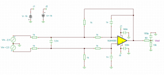
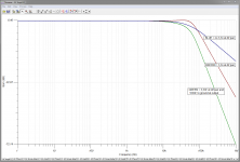
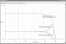
Here simulation circuit and plots, 1-circuit, 2-amplitude, 3-groupdelay.
Green and blue is with and without 3,3nF cap between dif, green is the 100pF at output changed to 100nF probably as you did.
Don't no if groupdelay changes in highs at uS is audioable, but there's a difference in plots.
Late, bed calls.
Attachments
Last edited:
But think about it, and I am thinking this is also ESS's thinking, that an output Z ranging from 781.25 Ohm (single phase) to 195.31 Ohm (four phases) into a Virtual Earth (supposedly Zero Z), then even though the DAC looks rather low Z, the ratio is still theoretically infinite if the termination Z is Zero (and that is where the cap stop working).
(Not sure what the output Z of a Burr-Brown PCM1792-1798 is - I have only seen the rated current output and assuming infinite.)
So it is the termination impedance rather that send impedance that determines "current" mode, the ratio. But if the termination Z is not Zero, then what ratio is acceptable? I would say 10:1, but preferably a lot higher than that. My ratio is 118 with two phases ((781/2)/3.3).
So this gives "current" mode and yet also a place to put that cap.
Cheers, Joe
Hi Joe,
This is an interesting point. Indeed, the ratio between the DAC Zout and the I/V Zin determines how 'current mode' it is. But to a first order, this is not terrible important. What IS important is how linear that Zout and Zin is over the signal cycle. If those impedances vary over the signal cycle, you have harmonic distortion - even order if the variation is assymmetric, odd if symmetric.
So an I/V input of non-zero ohms in itself is no issue, as long as it is constant over signal level (assuming the DAC output, like the 761 ohms of the ESS, is also constant over level)!
Jan
It differ:
Filter cap to ground gets highs comes before middle/lows (groupdelay) to our ears.
Filter cap between dif pair gets opposit groupdelay highs after middle/lows, or at least less speedy in highs.
At same if any HF noice at DAC output it gets some filter before next device, and last the dampening in highs.
I don't believe there is any difference. You can consider two caps to ground from each phase as two caps in series between the phases. In both cases the midpoint is at zero. The only difference is that in your case you need two caps of double the capacity for the same roll-off.
Jan
Hi Joe,
This is an interesting point...
So an I/V input of non-zero ohms in itself is no issue, as long...
Yep, we are on the same page.
Cheers, Joe
.
Hi Joe,
This is an interesting point. Indeed, the ratio between the DAC Zout and the I/V Zin determines how 'current mode' it is. But to a first order, this is not terrible important. What IS important is how linear that Zout and Zin is over the signal cycle. If those impedances vary over the signal cycle, you have harmonic distortion - even order if the variation is assymmetric, odd if symmetric.
Jan
I would try another approach, although the afore quote about Zout could be a fine idea:
We had to imagine, that all mentioned S/D-DAC-chips use the time-slice mode. That means, that the actual output current is a time-slice of a steady CCS, giving Imax @ 100% PWM. The inverted output acts the opposite. If we now integrated this slice over time, we found the actual value. If you actually had a look at your scope and inserted a steady signal into the DAC, you could see the artifacts of the time-slicing. Varying the load, gives more or less of these artifacts. Try it using a triangle wave and you will find the artifacts at some other part of the trace - if you varied the load. So I would not presume, that we can speak of a linear or maybe a/symmetric variation of Zout. I would say, that we cannot describe any sudden Zout because it depends on the time-slice variation only!
I have to say, that my research two years ago went on only using PC1798 and some other similarly built DACs so I cannot tell about the ESS chip. I have an ESS 9018 evaluation board and would like to go further with it ...
I do not want to start another discussion, if this is a filter or not, but my research reminded me more on that assembly to be an integrator. What is important too, is the fact, that the performance kept low, as long as the active part of the I/U was still differential. So I coupled a triode to the inverted path using its nearly infinite ohms impedance to have no load to the DAB. And BINGO ... that worked.
You may find the schematic of the DAB here DAB.
The opt. values for the PCM1798 are: R1 and R3 = 22 ohm, R2 and R4 = 82 ohm, C1 is 15nF. Forget for the moment the ferrite bead as it works without too - just showing a bit more noisefloor. Performance depends widely on the quality of C1, so I presumed, that it plays the main role.
My calculation:
There are three possible current paths from both outputs (e.g. JP1-Iout+):
R1->R2->GND (purely resistive; 104 ohm)
R1->C1->R3->Iout- (integrating; 660ns)
R1->C1->R4->GND (filtering; app. <100kHz)
These are the values for the DAB only, of which I would estimate really some interaction with the varying Zout of the chip itself.
At last I had to say, that all of my calculations done prior to testing failed to some extent and the given values were found by trial and error...
What do you think about this approach?
This forum is inclusive. All contributions are permitted (if reasonably polite), including those pointing out elementary technical errors in the contributions of others.Joe Rasmussen said:We need to keep them in mind too - why do you think they are silent? We are the most likely the reason they are - they fear us for what they might say here, that their 'knowledge' will come up short. Yet they too should have a right to have a voice.
We should be more inclusive and less exclusive.
Newbies are welcome, especially if they are keen to learn. Occasionally one pops up who prefers to remain clueless but fortunately these are rare.
There is one group which can sometimes feel they get a hard time on here: those with the experience of an expert, but the knowledge of a newbie. They can feel that their vast experience (and, in some cases, sales?) gives them some sort of authority, so they don't like being corrected. I usually don't know who they are until they tell me themselves.
So people who are keeping quiet should join in, if they have something useful to contribute. I kept quiet (in this thread) until I had something to say.
I usually don't know who they are until they tell me themselves.
True. For the most part what you say is right, but there are many who just read the forums as well and I think we should foster an environment that encourages more to feel comfortable and have a voice too.
But it does seem that the forum now has settled down a bit.
Cheers, Joe
I don't believe there is any difference. You can consider two caps to ground from each phase as two caps in series between the phases. In both cases the midpoint is at zero. The only difference is that in your case you need two caps of double the capacity for the same roll-off.
Big difference versus common mode noise coming out of the DAC, which is unknown...
2 Capacitors to ground will filter out common mode noise, but the difference in their values will turn some of the common mode noise into differential. One capacitor between pos and neg differential lines will not filter out common mode noise but will also turn common mode noise into differential if the source impedances are mismatched...
What is important too, is the fact, that the performance kept low, as long as the active part of the I/U was still differential. So I coupled a triode to the inverted path using its nearly infinite ohms impedance to have no load to the DAB. And BINGO ... that worked.?
Maybe it comes from the fact that RF noise at the input tends to give severe constipation to opamps, whereas tubes don't care. I have plans somewhere for a RF modulated noise source to check this...
Last edited:
Big difference versus common mode noise coming out of the DAC, which is unknown...
2 Capacitors to ground will filter out common mode noise, but the difference in their values will turn some of the common mode noise into differential. One capacitor between pos and neg differential lines will not filter out common mode noise but will also turn common mode noise into differential if the source impedances are mismatched...
Yes, agree to your reasoning.
But, by the same token, the caps to ground can easily couple ground noise into the signal lines. After all, the whole point of going balanced is to avoid having to use ground as a reference, and by putting caps from output to ground you throw away all you have gained going balanced.
Jan
Differential outputs on DACs are meant to reject the on-chip ground and power supply noise... but a few cm away if you have noise on your ground plane, then you have a big problem...
Also the 2 caps to ground can connect to the same ground point : if this point is noisy it will inject common mode noise, not differential (depending on impedance imbalances etc).
Also the 2 caps to ground can connect to the same ground point : if this point is noisy it will inject common mode noise, not differential (depending on impedance imbalances etc).
- Status
- Not open for further replies.
- Home
- Member Areas
- The Lounge
- DAC Filtering - the "Rasmussen Effect"