I have also intuitively supposed that it may happen something in this "phases" domain of the signal`s components (post 84), when using this filtering technique. What is happen with these harmonics, it seems to me as quite reasonable in Barbara`s theory. This cap over DAC outputs it may disturb (unbalance) the "perfection" or the functional level of the following I/V circuit, so that the more harmonics (of the audio signal) are to be outputted from the audio system. This it can make the brain (based on more informations) to appreciate better the location of the sound sources in sound space/scene.
I think it may be enough plausible so how the mechanism works in this case, to generate perceptual improvements, better defined , more open sound scene, better resolution in it, and so on. How it may also work the electrical mechanism in the present case, is to be further discussed... I can see already too, that Jan do not agree with this theory...
Now it looks to me that calling this as "filtering" technique it may not be quite appropriate. It will be better be called "unfiltering" or "signal disturbing" technique... to get a very positive result...
Last edited:
Hi Jan,
That was my initial thinking too! Did you read the article I posted? Or simply try it out.
Again you are right about even harmonics generated inside the chip, my measurements showed, that odd order will sum - awfully! BTW - you can find ready-to-use test signals at my website.
BR, Barbara
That was my initial thinking too! Did you read the article I posted? Or simply try it out.
Again you are right about even harmonics generated inside the chip, my measurements showed, that odd order will sum - awfully! BTW - you can find ready-to-use test signals at my website.
BR, Barbara
It could prevent the DAC from getting upset about a big capacitor hanging there.
No, because there is already an 800 ohms internal R. Ten more ohms won't make a difference.
Jan
I have also intuitively supposed that it may happen something in this "phases" domain of the signal`s components (post 84), when using this filtering technique.
Why do you keep calling it a 'technique'? It's just a standard, simple 6dB oct low pass filter.
You call it a technique as if it's the best thing since sliced bread.
Go over to the non-filtered DAC religion, they are mordicus agains ANY filtering because it upsets the phase response which - in their ears - hurts the signal quality. Go figure.
And yes, ALL filters will also introduce a phase shift, the amplitude and phase response are locked. The steeper the filter, the larger the phase shift.
Jan
Do we know it's 800 ohms physically or is it some resistance and it's reduced by feedback? That's why I said it could, not that it would.No, because there is already an 800 ohms internal R. Ten more ohms won't make a difference.
Jan
That's what I find so bothering too. It's been nothing but a filter all along. He's the only one here not grasping it.Why do you keep calling it a 'technique'? It's just a standard, simple 6dB oct low pass filter.
Do we know it's 800 ohms physically or is it some resistance and it's reduced by feedback? That's why I said it could, not that it would.
I suspect it is physical but not sure. But that is immaterial. The point is that if you load down the output, the output level decreases as if there's an 800 ohms (I think Joe knows the exact value, something like 740 I think).
That means it looks, feels and acts as an 800 ohms resistor, and your circuit acts as if there's an 800 ohms resistor.
I have another example of this. If you have a power amp, the output impedance increases (damping factor decreases) with frequency. The reason is that the feedback gets less and less effective at higher frequencies.
So there's no physical component or anything that causes it.
BUT what component increases in impedance with frequency? Yes, a coil, 100 points! So people 'in the know' say: the output impedance of a power amplifier is inductive! Because the amp acts as if there's an inductor in the output. And, funny enough, if you capacitively load the power amp with a capacitor of the right value, the 'inductive' Zout and the cap start to resonate as if there's a real inductor. Which has led to the untimely demise of many a power amp, but that's another story.
Jan
PS Yes I know in some power amps there's a small coill but that's not what I mean. Without that coil the Zout is still inductive and shows all signs of a physical inductor including the tendency to oscillate with the right cap.
Do we know it's 800 ohms physically or is it some resistance and it's reduced by feedback? That's why I said it could, not that it would.
From what I think I know :
The output stage seems to be around 64 thermometer encoded switches. Each switch connects either AVCC or AGND to pin 1 of its own resistor. Pin 2 of all the resistors are connected to physical output. All the resistors in parallel make about 800 ohm. So it is equivalent to a voltage source, impedance 800 ohm. It is duplicated for each polarity of each DAC (so there are 16 of those on chip).
Dustin says it is better to connect the output to a low impedance because the resistors have a voltage coefficient. It also makes the current draw on AVCC constant.
Very interesting! Thanks for the explanation.From what I think I know :
The output stage seems to be around 64 thermometer encoded switches. Each switch connects either AVCC or AGND to pin 1 of its own resistor. Pin 2 of all the resistors are connected to physical output. All the resistors in parallel make about 800 ohm. So it is equivalent to a voltage source, impedance 800 ohm. It is duplicated for each polarity of each DAC (so there are 16 of those on chip).
Dustin says it is better to connect the output to a low impedance because the resistors have a voltage coefficient. It also makes the current draw on AVCC constant.
Edit: Do you know if those switches are make-before-break? Is there a chance that the output open circuits during transitions?
Last edited:
AC dampening effect in highs, less ringing and therefor more tight clear sound stage ? (AC dampening very audioable on speakerdrivers, and snoopers elsewhere are popular).
Groupdelay in highs ? (Highs get slowed and counteracts other chain devices tendency to present highs before lows).
Don't know, just inputs.
Groupdelay in highs ? (Highs get slowed and counteracts other chain devices tendency to present highs before lows).
Don't know, just inputs.
Attachments
Last edited:
For exactly the same reason the virtual ground at an inverting opamp input is also inductive - this seems to be less well known. Adding a capacitor in parallel risks creating a resonator. This could increase distortion by raising the amount of HF entering the opamp. The result could be misintepreted as increased 'detail' etc.jan.didden said:So people 'in the know' say: the output impedance of a power amplifier is inductive!
Why do you keep calling it a 'technique'? It's just a standard, simple 6dB oct low pass filter.
Jan
Yeah, I can agree that "technique" it may not be the best word to be used in this case. I was only thinking that placing that filter in that place, it may be called "technique", as this is not a very usual way or use a filter...
Else, I do not have something against to be used another related expression...🙂
Ops! I was off topic with this linguistic subject here...😀
I'm looking forward to it. Although I doubt it's audible, it could explain the difference you saw in the switching noise. Hypothesis: The capacitor prevents a sudden change in voltage due to bias currents during the time it's open circuited. Of course if you find that impedance doesn't change during switching the previous wouldn't be the case.Fomoco : Don't know. If all goes well I'll be able to measure that stuff soon.
I personally don't think it's audible, especially not being described as a more tight clear soundstage, but it's definitely going to affect frequency and phase response a little bit.AC dampening effect in highs, less ringing and therefor more tight clear sound stage ? (AC dampening very audioable on speakerdrivers, and snoopers elsewhere are popular).
Groupdelay in highs ? (Highs get slowed and counteracts other chain devices tendency to present highs before lows).
Don't know, just inputs.
That's why I previously posted that this is a bad way to implement a filter. No one seemed to believe that it could cause stability problems. Although the resistors Joe added as the discussion went on probably mitigates this problem.For exactly the same reason the virtual ground at an inverting opamp input is also inductive - this seems to be less well known. Adding a capacitor in parallel risks creating a resonator. This could increase distortion by raising the amount of HF entering the opamp. The result could be misintepreted as increased 'detail' etc.
That's why I previously posted that this is a bad way to implement a filter. No one seemed to believe that it could cause stability problems. Although the resistors Joe added as the discussion went on probably mitigates this problem.
Yes the resistors definitely help in the stability department.
This is exactly the same considerations you have to look at for photodiode recevers. The photodiode delivers a current and the I/V conversion is done by a specialised opamp. The opamp is specially designed to have extremely low capacitance at the input, often just a few pF. So the last thing you need is adding capacitance there!
Jan
I was only thinking that placing that filter in that place, it may be called "technique", as this is not a very usual way or use a filter...
It is THE standard way to filter a balanced signal, it is done all the time. You may not be aware of it, and that happens to all of us once in a while, but normally you'd do at least some Google research before going off on a tangent. Helps saving your teeth 😉
jan
For exactly the same reason the virtual ground at an inverting opamp input is also inductive - this seems to be less well known. Adding a capacitor in parallel risks creating a resonator. This could increase distortion by raising the amount of HF entering the opamp. The result could be misintepreted as increased 'detail' etc.
Finally 😀 😉
Just as peufeu shows some hundreds of post ago 😎
It's quite normal.
It's easy to measure it, but involved people don't want to show us. 🙄
After 200 author's post of "no, it's not a filter", now "it's a filter".
Who wrote "it's a filter" in past was filed as hereptic.
And after acclaim that humans can hear above 20kHz, you place a filter with -1dB @20kHz? 😀😀😀 wtf?!
Take a decision

Anyway..ideal CS doesn't exist. "Ideal" doesn't exist at all😛
It is THE standard way to filter a balanced signal, it is done all the time. You may not be aware of it, and that happens to all of us once in a while, but normally you'd do at least some Google research before going off on a tangent. Helps saving your teeth 😉
jan
OK, I get it...
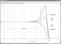
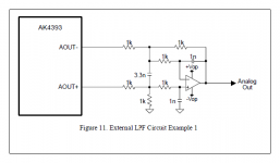
Though if you want to split hairs, the R against which the cap works would be the 2 x 3R3 in parallel with the 2 x 800 + 10 ohms. ohms, but 3R3 is close enough. 😉
Oh indeed yes, the drive Z is actually the equivalence of a resistor driven by Zero Z. So there has to be perceived there are two points where at the beginning and at the end, there has to be to Zero Z points, otherwise how are we to define the operation of the filter. It has to be 'ground' referenced at two places.
But think about it, and I am thinking this is also ESS's thinking, that an output Z ranging from 781.25 Ohm (single phase) to 195.31 Ohm (four phases) into a Virtual Earth (supposedly Zero Z), then even though the DAC looks rather low Z, the ratio is still theoretically infinite if the termination Z is Zero (and that is where the cap stop working).
(Not sure what the output Z of a Burr-Brown PCM1792-1798 is - I have only seen the rated current output and assuming infinite.)
So it is the termination impedance rather that send impedance that determines "current" mode, the ratio. But if the termination Z is not Zero, then what ratio is acceptable? I would say 10:1, but preferably a lot higher than that. My ratio is 118 with two phases ((781/2)/3.3).
So this gives "current" mode and yet also a place to put that cap.
Cheers, Joe
Last edited:
Finally 😀 😉
After 200 author's post of "no, it's not a filter", now "it's a filter".
Who wrote "it's a filter" in past was filed as hereptic.
The only one confused it you.
I have called it a filter from the beginning - another straw man argument?
Can we put this ego stuff behind us?
.
- Status
- Not open for further replies.
- Home
- Member Areas
- The Lounge
- DAC Filtering - the "Rasmussen Effect"