At the output of what? The DAC chip output terminals, or at the end of the analogue chain of the D/A converter box?I actually (somewhat) tried this. I'm not willing to modify equipment to prove something that isn't all that important, but I did implement a low pass filter (at the output) with an F3 of about 30 kHz.
The RCA outputs. Specifically at the point the signal would enter the receiver. Since the effect is from filtering, and not magical interaction, this should work as well.At the output of what? The DAC chip output terminals, or at the end of the analogue chain of the D/A converter box?
Joe, of course, the cap has to see a voltage across it to do anything. But a cap across the I/V inputs, which I believe is what you show, cannot do anything because the I/V inputs are at zero volts (virtual ground).
Hi Jan
Isn't this beside the point?
Did I not say to implement the filter the way you see fit, and did I not call them "Suggestions" ???
Please read it again.
But my "Suggestion" re the output of "current" DACs is based on Thevenin's Theorem.
I use it to calculate and also model loudspeakers to be "I" driven. To me is bread and butter stuff.
The DAC will still output the same current. If it sees a zero Ohm load, any cap at that point will make no difference. But insert a resistor between the cap and the zero Ohm point, then a voltage will develop across that resistor and hence the cap will see a voltage. Then it will filter.
_______________________________________________________________
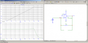
In order to verify it, I just ran the simulation in CircuitMaker, very easy to do:
Current Out: 4mA P/P
Opamp: Ideal
I/V Resistor on Ideal Opamp: 1K
Mad Cap: 10.000uF
Series Resistor after Cap into I/V Converter: 1 Ohm
Extreme circumstances, but they worked to illustrate what happens.
Without the 1 Ohm resistor, the cap, even though I made it 10.000uF, made no difference. Exactly as I expected.
Add just a little resistance after the cap, just one Ohm and the output was totally killed by the cap at the output of the I/V Converter.
So that small resistance killed it, but how if there is no voltage across the cap?
Logic tells us, that while the out of the Opamp is an absolute zero, then a voltage must still be across the cap.
Follow so far?
Then I put the 'probe' on that 10.000uF cap and there was indeed a voltage, albeit the tiniest of the tiniest amount, a minuscule 1.25nV
As soon as the tiniest voltage appears across the cap, when using a monster cap value, will kill the final output, even though there is still a tiny voltage across the cap.
Effectively, that 1 Ohm Resistor and 10.000uF are in parallel - that makes them an RC filter.
Cheers, Joe
PS: BTW, remove the cap gave me near 1.5V output.
PPS: I wasn't wrong about the filter, but the values in the diagram are way off - mea culpa - I think that 1nF used by Coris was a pointer to that already.
.
Attachments
Last edited:
I re-ran the simulation to that of the diagram - and those shown values do figure out correctly, with 2 x 3R3 and 0.82uF.
It the DAC was single-ended, then 3R3 and 1.64uF (2 x 0.82uF) would get the target around -1.4dB.
Cheers, Joe
PS: The current has to go somewhere, think of those series resistor as current being dumped into them (the far side of the resistor is 'grounded'), so there is current across those resistors, AC current. Once than happens on both those resistors, AC signal current will start to flow through the cap. Where does the current go? To the other phase, it's gets cancelled.
Now there is less current going through those resistors, the final out is less as the current that gets I/V'd is less.
It's a filter!!!
.
Last edited:
So your calculation of the cap value based on the two resistors alone is incorrect.
Not a calculation. Actually a guesstimate that proved remarkably accurate.
Now peufeu had a good point, that with increasing frequency, the I/V may depart from the ideal and actually show some residual voltage, and that may be affected by the cap. Maybe we should try to quantify that and/or measure that.
Lets not forget that even if the I/V departs from ideal, and shows some residual voltage, still the effective impedance of the I/V will be small
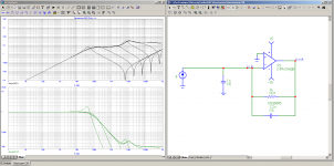
Well, the input impedance of the IV is :
((opamp open loop output Z) + (feedback network Z)) / (open loop gain)
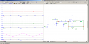
See attachment 1. Top curve is IV input impedance, bottom is output voltage. 1 mA current in, 1k resistor, 1V out.
When frequency rises, open loop gain is falling, so impedance is rising.
When we reach the filter cutoff point, here -3dB at about 70kHz, the feedback cap takes over and the lowering of its impedance compensates the loss of open loop gain, so we reach the flat part of the IV input impedance curve, here its about 6 ohm, this may vary a lot depending on the opamp.
Around 10 MHz open loop gain runs out, so it is mostly the opamp's open loop output impedance, feedback cap, and parasitics.
Second plot, without feedback cap, no surprise here, the input impedance is 1k divided by open loop gain, and gets pretty high pretty fast at HF. The output curve is an illusion of AC analysis, opamp slew rate limit will kick in long before the apparent 10 MHz cutoff.
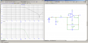
But what is the residual voltage at the input ? (That is the question to ask...) well, it depends on the frequency content of the DAC output waveform, and therefore, it depends a lot on its slew rate.
Third graph, let's add a cap (stepped from 1p to 1u) at the input. It makes a lowpass with the input impedance, but this is pretty low, so a large cap (100n) is needed to have an effect. It also makes the opamp go a little unstable. It also boosts the noise gain and output noise enormously... without the feedback cap, the opamp will oscillate.
4th graph, a resistor is added at the opamp output. In this case, back to the classics, we have a current divider between Cin and (Rin+IV's Z) and the RC lowpass frequency is calculated the usual. Of course the impedance seen from the DAC is now much higher... we could reduce Rin to a much lower value but the noise gain problem comes back, then.
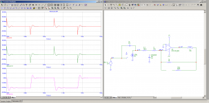
OK, what does it look like in the time domain ?
5th graph, classic IV, connected straight to the DAC.
I've used a 5ns risetime for the DAC output (for lack of a known value).
Opamp input stage gets overloaded a little. TIM will result.
IMHO, here, the simulation isn't very realistic, since opamp supply impedance is not modeled (and it is not possible to spice it with these opamp models).
6th graph : The usual audiophile "decoupling" "capacitors" being leaded films with huge (10-20nH) inductance, plus traces, to get a rough idea, I'll put a 30nH inductor in the opamp output. This is probably quite optimistic. Things get ugly.
7th graph, same, without feedback capacitor. Why not. The opamp's input stage is thoroughly raped, the output slew limits, etc. Loads of TIM are produced here.
8th graph, add cap at the opamp's input : it looks much better... much less spikes... However I have put the cap to GND. In a differential system, the cap between +/- lines would only remove differential noise.
Attachments
-
 iv_input_z.png23.2 KB · Views: 311
 -
 iv_input_z_2.png22.7 KB · Views: 313
 -
 iv_input_cap_1.png26.9 KB · Views: 300
 -
 iv_input_cap_2.png23.4 KB · Views: 277
 -
 iv_input_cap_transient_1.png23.2 KB · Views: 119
 -
 iv_input_cap_transient_2.png23.2 KB · Views: 125
 -
 iv_input_cap_transient_3.png22.9 KB · Views: 127
IMHO, here, the simulation isn't very realistic
Yours or mine?
I am trying to figure out what your point is. Could you please sum up?
.
The RCA outputs. Specifically at the point the signal would enter the receiver. Since the effect is from filtering, and not magical interaction, this should work as well.
😀😀 Now is clear that we talk about something, while you think at something else. You may understand that this (a filter) it have different effects up to the place it is placed into the system, or in the signal path.
We talk about here to apply a filter (this cap) on the differential (+/-) outputs of the DAC chip. This is that which bring the improvements we talk about. Applying the cap or a filter on the RCA outputs it spoil everything for the audio signal. We are into the device black box with this filter, not at its output, or at a receiver (anther black box) input...
I just wonder how you did not knew about this simple fact, and what this discussion is about here...
Last edited:
Yours or mine?
Both.
I am trying to figure out what your point is. Could you please sum up?
That what is going on is not simple filtering.
Coris said:We talk about here to apply a filter (this cap) on the differential (+/-) outputs of the DAC chip. This is that which bring the improvements we talk about. Applying the cap or a filter on the RCA outputs it spoil everything for the audio signal
Then the effect does not come from the filter rolloff inside the audio band. If that was the case, it would work the same when it is at the output.
Last edited:
I know exactly what it is about. My reply to Joe explained why I chose that point. He has stated all along that it's just filtering that is responsible for the effect. In that case, what I did should have worked. In his response, he stated that he felt the chosen f3 wasn't right. Go back and read it. It is you that doesn't understand. Besides, I thought you were done replying to me.I just wonder how you did not knew about this simple fact, and what this discussion is about here...
Joe:
Still waiting for a different F3 value to try. You said the one that I tried (the one that fits the example you gave) was wrong. Tell us the right one. As of now you're changing things as we go along and still admonishing the nonbelievers. Still looks like heresy to me.
Unless it's so subtle that I (and all of us evil dissidents) couldn't hear it.Then the effect does not come from the filter rolloff inside the audio band. If that was the case, it would work the same when it is at the output.
Could be it's the result of a non-perfect interaction as you've stated. In that case, the "effect" would be different on each piece of equipment it was tried on. If that's true, it would be luck of the draw for each person who tries this.
NITRO - DAB
Hi Mr. Rasmussen,
two years ago I found similar effects too. I called my solution "DAB" (for Digital Audio Balun). You can read the whole story at my website ->
NITRO-DAB
My research gave, that this effect - you now describe too - is based on some kind of integration of both of the inverted output currents. Because I only tapped one side it is the perfect differential (balanced) to single-ended (unbalanced) converter.
This method has a measurable impact on the playback of even order harmonics too. Maybe therefore the impression is to have better resolution and better details, since even order harmonics improve understandability as well as imaging and increase the ability to distinguish many different colorings of sounds.
Best regards, Barbara E. Gerhold
<tubeclinic>
The DAC will still output the same current. If it sees a zero Ohm load, any cap at that point will make no difference. But insert a resistor between the cap and the zero Ohm point, then a voltage will develop across that resistor and hence the cap will see a voltage. Then it will filter.
Agreed. Didn't see that particular circuitry; there's too much talk and not enough pictures (which as you know are worth about 1000 words each 😉).
BTW Doesn't the ESS DAC have about 800 ohms output resistors build-in at each phase?
So what does that do to the correct value of the cap? Anybody wants to tackle that one?
Or maybe more generally: suppose the following situation: output R 800 ohms, out build R 10 ohms per phase, then the cap, then another resistor (10 Ohms?), then the I/V input (please Joe correct values if I have them wrong).
Q: what value of resistance would you use to calculate the cap for say a 20kHz roll off?
Jan
Well, the input impedance of the IV is :
((opamp open loop output Z) + (feedback network Z)) / (open loop gain)
See attachment 1. Top curve is IV input impedance, bottom is output voltage. 1 mA current in, 1k resistor, 1V out.
When frequency rises, open loop gain is falling, so impedance is rising.
When we reach the filter cutoff point, here -3dB at about 70kHz, the feedback cap takes over and the lowering of its impedance compensates the loss of open loop gain, so we reach the flat part of the IV input impedance curve, here its about 6 ohm, this may vary a lot depending on the opamp.
Around 10 MHz open loop gain runs out, so it is mostly the opamp's open loop output impedance, feedback cap, and parasitics.
Second plot, without feedback cap, no surprise here, the input impedance is 1k divided by open loop gain, and gets pretty high pretty fast at HF. The output curve is an illusion of AC analysis, opamp slew rate limit will kick in long before the apparent 10 MHz cutoff.
But what is the residual voltage at the input ? (That is the question to ask...) well, it depends on the frequency content of the DAC output waveform, and therefore, it depends a lot on its slew rate.
Third graph, let's add a cap (stepped from 1p to 1u) at the input. It makes a lowpass with the input impedance, but this is pretty low, so a large cap (100n) is needed to have an effect. It also makes the opamp go a little unstable. It also boosts the noise gain and output noise enormously... without the feedback cap, the opamp will oscillate.
4th graph, a resistor is added at the opamp output. In this case, back to the classics, we have a current divider between Cin and (Rin+IV's Z) and the RC lowpass frequency is calculated the usual. Of course the impedance seen from the DAC is now much higher... we could reduce Rin to a much lower value but the noise gain problem comes back, then.
OK, what does it look like in the time domain ?
5th graph, classic IV, connected straight to the DAC.
I've used a 5ns risetime for the DAC output (for lack of a known value).
Opamp input stage gets overloaded a little. TIM will result.
IMHO, here, the simulation isn't very realistic, since opamp supply impedance is not modeled (and it is not possible to spice it with these opamp models).
6th graph : The usual audiophile "decoupling" "capacitors" being leaded films with huge (10-20nH) inductance, plus traces, to get a rough idea, I'll put a 30nH inductor in the opamp output. This is probably quite optimistic. Things get ugly.
7th graph, same, without feedback capacitor. Why not. The opamp's input stage is thoroughly raped, the output slew limits, etc. Loads of TIM are produced here.
8th graph, add cap at the opamp's input : it looks much better... much less spikes... However I have put the cap to GND. In a differential system, the cap between +/- lines would only remove differential noise.
Nice! Thanks,
Jan
Agreed. Didn't see that particular circuitry; there's too much talk and not enough pictures (which as you know are worth about 1000 words each 😉).
Agreed, but I have now posted three examples/pictures.
BTW Doesn't the ESS DAC have about 800 ohms output resistors build-in at each phase?
Yes it does, so it depends on how many phases you parallel up. It's actually 781.25 Ohm and if the load approaches Zero Ohm it effectively operates in current mode. I run it into 3R3 per side.
So what does that do to the correct value of the cap? Anybody wants to tackle that one?
That 3R3 x 2, and I use 0.78uF or 2 x 0.39uF.
This is one instance that I can be fairly specific. Note that this is indeed passive I/V - but since the DAC sees its own Output Z so dominantly and 3R3 is so small it hardly sees it, so it is still in current mode.
I had a discussion some time ago with an engineer who had a thing about current modes, and I pointed out to him that a "voltage" interface is, according to convention, should have no more than 1dB insertion loss. So basically as a rule of thumb, the source should have no more than 1/10th output Z of the load, or it will sag more than 1dB.
So if that is the case, and following the same convention, then to qualify as "current" interface, the source Z should be at least 10 times the Load. He agreed that was reasonable.
So 10 times 3R3... or 10 times 6R6... and we have hundreds of Ohm Source Z, I think that qualifies handsomely.
But since those resistors define the Z, then the input impedance of the active circuit should be relatively high.
Does the above make sense to you?
Cheers, Joe
.
I called my solution "DAB" (for Digital Audio Balun). You can read the whole story at my website ->
NITRO-DAB
Hi Barbera
That is very interesting and I will take a little time to look at it and digest it.
I am hoping others will also do the same and not just make rash statements/judgments.
But what is interesting is that there is a mechanism at work, and one that has been described (not by me) as not subtle - quite obvious once heard.
Nearly midnight here - but will get back to this.
Cheers, Joe
PS: Please, no more of this "Hi Mr Rasmussen" - I am just a plain Joe
.
NITRO-DAB
Hi Joe, Hi Coris,
THX for your quick answer. In my case of tapping only one side of the DAB for I/U-conversion to SE, acc. to my measurements I found, that the increase in performance is mainly due to the fact, that all harmonics from the recording are treated equally. You can use the test signals from my website <tubeclinic> and try by yourself.
This is not the fact in any differential system, since here the even order harmonics are detected as a common-mode signal. And well, the more precisely such a diff. system works, the better the deletion!
Think about that please, I did experiments too in adding a conventional OPA-I/U-converter behind the DAB and that failed similarly!
@ Joe: I think that your calculations are fully right because they correlate well with my measurements/findings. Maybe you should think about a SE-tube stage for the output too ... 😉
BR, Barbara
Agreed, but I have now posted three examples/pictures.
Yes it does, so it depends on how many phases you parallel up. It's actually 781.25 Ohm and if the load approaches Zero Ohm it effectively operates in current mode. I run it into 3R3 per side.
That 3R3 x 2, and I use 0.78uF or 2 x 0.39uF.
This is one instance that I can be fairly specific. Note that this is indeed passive I/V - but since the DAC sees its own Output Z so dominantly and 3R3 is so small it hardly sees it, so it is still in current mode.
I had a discussion some time ago with an engineer who had a thing about current modes, and I pointed out to him that a "voltage" interface is, according to convention, should have no more than 1dB insertion loss. So basically as a rule of thumb, the source should have no more than 1/10th output Z of the load, or it will sag more than 1dB.
So if that is the case, and following the same convention, then to qualify as "current" interface, the source Z should be at least 10 times the Load. He agreed that was reasonable.
So 10 times 3R3... or 10 times 6R6... and we have hundreds of Ohm Source Z, I think that qualifies handsomely.
But since those resistors define the Z, then the input impedance of the active circuit should be relatively high.
Does the above make sense to you?
Cheers, Joe
.
Yes it does, well explained. Though if you want to split hairs, the R against which the cap works would be the 2 x 3R3 in parallel with the 2 x 800 + 10 ohms. ohms, but 3R3 is close enough. 😉
It should also be clear that the two 10 ohms at the DAC output have no purpose. Or maybe that's already gone from your latest scheme.
jan
This is not the fact in any differential system, since here the even order harmonics are detected as a common-mode signal.
I don't think this is correct. The harmonics in the recording are part of the signal. If you have a balanced version coming out of the DAC, the original harmonics are also balanced i.e. in opposite phase just like all other parts of the signal and will not cancel. The system does treat everything in the signal the same.
The cancellation of harmonics only comes into play with harmonics generated by the DAC as these *can* be in the same phase in each output and if so, they will cancel.
Jan
It should also be clear that the two 10 ohms at the DAC output have no purpose. Or maybe that's already gone from your latest scheme.
It could prevent the DAC from getting upset about a big capacitor hanging there.
- Status
- Not open for further replies.
- Home
- Member Areas
- The Lounge
- DAC Filtering - the "Rasmussen Effect"