Look like if I don't want to solder jumper wires it will have to be placed on the underside of the board. Any potential problems with that?
I think it is much better to solder the SC transformer underside, IMO, I believed that pin 4 and 5 should be used for signal in and out.
I plan to use 4/5 as you mentioned. If there's no penalty to putting it under the board it makes the most sense.
Trim pot orientation
Post 34, 43 show one orientation.
Pots 88, 111, 127 show the opposite orientation.
Which is correct?
Post 34, 43 show one orientation.
Pots 88, 111, 127 show the opposite orientation.
Which is correct?
Post 34, 43 show one orientation.
Pots 88, 111, 127 show the opposite orientation.
Which is correct?
It was the introduction of the DAC that you have done, as you use their ingredients!
Orientation is what you see on the diagram, circuit.
1. DAC-END with a loss of money invested in the variable Output, (I still owe you this PCB)
2. DAC-end2 may have some stability in the TL431 shunt,
3. DAC-ASH give you a complete set of high-grade parts and separate sources - Salas shunt,
Therefore, investment in quality components, resistor capacitor as possible! And I'm sure you will not waste money and effort for this! Simply enjoy the music!
Sorry I'm bad with the orientation symbol of the trim/variable resistor. Is the arrow on the symbol point toward where the adjuster goes? Or away from where the adjuster goes?
I've put these in backwards in other projects before and had to unsolder them which as you know is a pain.
I've put these in backwards in other projects before and had to unsolder them which as you know is a pain.
Last edited:
you mount it on and adjust the voltage, Once, begin to plug the chip!
With the Trimmer Salas shunt does not affect too much the noise, do not worry!
Every afternoon was not necessary based on the direction of the arrow of trimmer
With the Trimmer Salas shunt does not affect too much the noise, do not worry!
Every afternoon was not necessary based on the direction of the arrow of trimmer
I am totally confused by your answer. I know what a trimmer does. Some boards have outline for where the screw should be oriented. Yours just has the schematic symbol. If I look under the board and see the voltage coming in I guess that is where the screw should be? Towards the front of the Salas shunt? Like 34/43 post?
When I did a test it appears to work better with the adjuster toward the input of the power supply.
When I did a test it appears to work better with the adjuster toward the input of the power supply.
I not understand you say?? can you tell me again??
Almost finished! 😀
Last question still is regarding the input SPDF transformer. Pin 8 is going to board ground. Shields need to go to board ground. Can I just tie them to pin 8? Or should they be tied together with a jumper wire going to a ground somewhere else?
Last question still is regarding the input SPDF transformer. Pin 8 is going to board ground. Shields need to go to board ground. Can I just tie them to pin 8? Or should they be tied together with a jumper wire going to a ground somewhere else?
Almost finished! 😀
Last question still is regarding the input SPDF transformer. Pin 8 is going to board ground. Shields need to go to board ground. Can I just tie them to pin 8? Or should they be tied together with a jumper wire going to a ground somewhere else?
Please se post #259!
Thanks!
Yes I see that. I chose 4/5 as input output. So now 8 goes to board ground where your drawing shows 5 to ground. My question is connections 6 & 7 which are the shields. Can they be tied to 8 all going to board ground or do they need a separate return by way of a jumper?
Yes I see that. I chose 4/5 as input output. So now 8 goes to board ground where your drawing shows 5 to ground. My question is connections 6 & 7 which are the shields. Can they be tied to 8 all going to board ground or do they need a separate return by way of a jumper?
Jum 1 to 2!@
The manufacturer said not to use 2 & 3. I'm thinking maybe the shields need to have their own return and not tie them to Pin 8?
Yes, how you guys cheat the GND? Is it the best way to use the point next to R52 on the I/V stage to connect the GND and the enclosure?
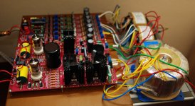
Completed the Dac-End 2 a couple weeks ago, using The tera-link X2. It is a significant upgrade to my system, still need to put it in an enclosure. I should have put it in a box first, before I hooked it up to my system. 😀
Completed the Dac-End 2 a couple weeks ago, using The tera-link X2. It is a significant upgrade to my system, still need to put it in an enclosure. I should have put it in a box first, before I hooked it up to my system. 😀
Hi! do you like the sound??
Well compared to my old cd player the sound of the Dac-end 2 is a vast improvement. Way smoother, very natural, and there is a tremendous amount more detail with the Dac-end 2. It did take a little while for the sound to open up, but that is to be expected. (the tera-link x2 was new as well.)
Building the Dac-end 2 was a tough and challenging build for me, and I learned a lot doing it. Now that I am listening to it though, it was absolutely worth the effort. I am happy and satisfied with the project.
Ben
Building the Dac-end 2 was a tough and challenging build for me, and I learned a lot doing it. Now that I am listening to it though, it was absolutely worth the effort. I am happy and satisfied with the project.
Ben
- Status
- Not open for further replies.
- Home
- More Vendors...
- Quanghao Audio Design
- DAC-ASH (dac-end 2 up date)