I needs 10v and 15v , what values of r1 r2 would you choose for the LT1963? Fixed, no pot...
ahah, that's more than okay as those days I diy à la slow food... snailishly in that word exists !
Glad to have to have your feedback. Miro's solution is good but thats 3 legs pots are a pain to me to remove...
It is possiblle I also wasted the pcb on the +V rail as I had pain to remove the 330R as it was rigth between the LDOs... hve to check with the DVM buzz continuinity option. But that's just the 150 R of my R1 that should be too much low
Last edited:
If you have a hot air blower, then it's easy.Glad to have to have your feedback. Miro's solution is good but thats 3 legs pots are a pain to me to remove...
Well, I don't drink. 😀
I rarely do that, and only beer. I've never been a fan of those specific hydrocarbons. I use more isopropyl alcohol.
I rarely do that, and only beer. I've never been a fan of those specific hydrocarbons. I use more isopropyl alcohol.

@diyiggy
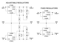
LT1963A fixed without trimmer:
15V in excel sheet:
R1 = 330R
R2 = 3760R (build with more different resistors in series)
10V in excel sheet:
R1 = 330R
R2 = 2400R
How can it be hard to use the excel sheet for fixed values without trimmer? Just let R1 330R and change only R2 with different values until you find desired voltage 😀
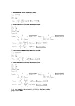
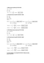
I simed R7 = 4k75 with R8 back to 330R (R1 datasheet) which is giving R2 (datasheet) = 1638 R (7.2V) to 2908 R (11,8V)
On the spreadsheet it works, but the trimpot amplitude is very big : 4,6V... not 1.2V !
Thanks miro, near 15V and near 10V is okay, so I can choose normalized values on the + rail and still work with trimpot on the negative rail to have the same negative V.
Just need to change the R-Core for 18V.
On the spreadsheet it works, but the trimpot amplitude is very big : 4,6V... not 1.2V !
Thanks miro, near 15V and near 10V is okay, so I can choose normalized values on the + rail and still work with trimpot on the negative rail to have the same negative V.
Just need to change the R-Core for 18V.
I think I damaged the pcb during the first desoldering process on r7 or r8 , the fuse is blowing with the BOM 5V values back ! Or maybe the LT1963
S....t no enough fuses left !
S....t no enough fuses left !
Last edited:
Here is a quick calculation for 5V, 10V, 12V and 15V. I kind of prefer the variant with fine adjustment, because it is difficult to achieve exact values with fixed resistors, and there are also the tolerances of the resistors and the regulators themselves. When you buy a fixed regulator, it also has deviations up to +/- 100mV. I think that this small deviation is mostly not important. And I have several voltmeters, none of them show the same voltage. Today, nothing can be trusted. 🤣
I think that for 15V there must be some pre-regulator in front to protect the LT1963 (it has a limit of max. 20V input voltage). One transistor, one resistor and one 20V zener diode is enough. The practical maximum for the LT1963 without a pre-regulator is approximately 13VAC secondary of the transformer.
I think that for 15V there must be some pre-regulator in front to protect the LT1963 (it has a limit of max. 20V input voltage). One transistor, one resistor and one 20V zener diode is enough. The practical maximum for the LT1963 without a pre-regulator is approximately 13VAC secondary of the transformer.
Attachments


Last edited:
Moja wersja DAC opiera się na układzie skalonym TDA1541. Jestem całkowitym amatorem. Skutki rzeczy pierwszy raz w życiu, oparcie na materiałach i schematach znalezionych w Internecie. DAC i zasilacz liniowy podłączony zoom777.


Moja wersja DAC opiera się na układzie skalonym TDA1541. Jestem całkowitym amatorem. Skutki rzeczy pierwszy raz w życiu, oparcie na materiałach i schematach znalezionych w Internecie. DAC i zasilacz liniowy podłączony zoom777.

English please.
My version of the DAC is based on a scaled TDA1541 system. I'm a total amateur. The effects of things for the first time in their lives, based on materials and schemes found on the Internet. DAC and linear power supply connected zoom777.
Hi,
Cool...
Please remove c28 that should be the dem external oscillator cap and any Networkgoing on pin 16 &17 as you have a non A chip... but for a precise reason like increasing the cap inside the non A. for active DEM sync.
I would remove too the 2 grey decoupling caps of pin -/+ 5 V pins... but if you choose the decoupling of -15V to -5V and try if better at listening if they only are decoupled to Agnd decoupled at the classic Agnd.
C1 to C5 remain to the Agnd ground. The gap that split Agnd to Dgnd should be also on the bottom layer, they cross only at pin 14
Last edited:

I don't know where my idea came from to order a transformer with 2x5VAC and 2x 12VAC outputs. PSU No. 2 needs only 2x12.If it doesn't work at 5VAC, he will surely ask what to do. 😁
Is 2x800mA sufficient current for AD1862?
Darek
Attachments
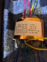
more than enough for the analog ad1862 side plus the opas. Maybe you took 5V for the digital side of the AD1862 that works between 5V to 12V. The original PSUII is +/-5V and +/-12V.
try to measure the AC of the 5V wires of the output of the traffo (not connected.). It is always less for R-Core than torroids. You need to have 5V + the dropping of two rectifier need and 0,xx V (very few) as it is a low drop out regulator (<LT1069/>LT3015).
try to measure the AC of the 5V wires of the output of the traffo (not connected.). It is always less for R-Core than torroids. You need to have 5V + the dropping of two rectifier need and 0,xx V (very few) as it is a low drop out regulator (<LT1069/>LT3015).
You can use 10V (5+5) for something else.I don't know where my idea came from to order a transformer with 2x5VAC and 2x 12VAC outputs. PSU No. 2 needs only 2x12.
Is 2x800mA sufficient current for AD1862?
Darek
800mA is total overkill.
- Home
- Source & Line
- Digital Line Level
- DAC AD1862: Almost THT, I2S input, NOS, R-2R