
The source is Tidal and Eversolo dmp A6. For the test I have connected 3 receivers from AliExpress. The first is wm8805, the second is the B18 selector on ak4118 and the third is the B37 selector on ak4137. Then they are connected to the i2s selector (for the test, to easily switch on the fly) and then to the dac. The cabling is temporarily the cheapest cables. Burson v7 vivid and classic opamp. It sounds really good to me but I also have a fiio k11 r2r and it generates a more holographic scene. This is the thing I want to improve the most. Are there any elements that particularly affect the sound that I could replace with better ones? The power supply is a psu1 and an r-core transformer.
@Tommar
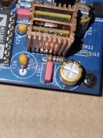
1. What is the I/V opamp in heatsink? Maybe you can try to change it for something another. I like LM6171 or you can also try OPA1655.
2. Desolder TR1, TR2, R4, R5, R6, R7 ...
3. Desolder C31, C36
4. What is the I/V resistor? Note that the value sets the output voltage from I/V.. R8, R9: output voltage from I/V (L-OUT, R-OUT), 1k4==1.4Vp, 2k4==2.4Vp, 2k7==2.7Vp (2.7Vp==5.4Vp-p)
5. C15, C16, C25, C26: the exact values must be maintained (ratio 1:10), consider a high quality electrolyte (now is tantallum) ... values like 4u7 + 47u , or 10u + 100u
😎
also check if both channels sounds the same, because I see different chips (they may come from ebay from some recycled device, it is mostly fine, but just to be sure)
I/V is Burson V7 Classic. I tried V7 Vivid and opa134PA but Classic is the best of the three. The seller claimed that the ICs are trimmed correctly but I can't confirm that. I asked him about different ICs and he said that there is no problem with that because they are trimmed. The I/V resistor is regular Carbon Film. What capacitors to use? It would be good if someone could suggest specific capacitors. How do I check if both channels sound the same? By ear?
Attachments
I have much earlier highlighted on 2,3,5 regarding this particular board when asked in DM... 🤣@Tommar
1. What is the I/V opamp in heatsink? Maybe you can try to change it for something another. I like LM6171 or you can also try OPA1655.
2. Desolder TR1, TR2, R4, R5, R6, R7 ...
3. Desolder C31, C36
4. What is the I/V resistor? Note that the value sets the output voltage from I/V.. R8, R9: output voltage from I/V (L-OUT, R-OUT), 1k4==1.4Vp, 2k4==2.4Vp, 2k7==2.7Vp (2.7Vp==5.4Vp-p)
5. C15, C16, C25, C26: the exact values must be maintained (ratio 1:10), consider a high quality electrolyte (now is tantallum) ... values like 4u7 + 47u , or 10u + 100u
😎
also check if both channels sounds the same, because I see different chips (they may come from ebay from some recycled device, it is mostly fine, but just to be sure)
The moment i see the pictures, my hands itches and i imagine myself heating up my soldering iron and removing the tantalum caps immediately without further consideration 🤣
if ordering from Mouser is fine with you , please refer to the caps recommended here for C15,16,25,26:I/V is Burson V7 Classic. I tried V7 Vivid and opa134PA but Classic is the best of the three. The seller claimed that the ICs are trimmed correctly but I can't confirm that. I asked him about different ICs and he said that there is no problem with that because they are trimmed. The I/V resistor is regular Carbon Film. What capacitors to use? It would be good if someone could suggest specific capacitors. How do I check if both channels sound the same? By ear?
The Nichicon KZ is already EOL, i think.
https://www.mouser.sg/ProductDetail/Panasonic/ECA-1HHG4R7I?qs=oMFZWh4gVt5Z7s8ImBlNLw==
https://www.mouser.sg/ProductDetail/Panasonic/EEU-FC1E470?qs=/UrJKH1balDrIEZEOcwNCg==
https://www.mouser.sg/ProductDetail/Panasonic/EEU-FC1C470B?qs=MtOUKumLmnbvkaDwU%2B%2BdyA==
https://www.mouser.sg/ProductDetail/Panasonic/EEU-FC1H101?qs=qGjfa/QGa0ujBwAMVh1bMQ==
Just some suggestions for you.
For those starting out on this build, please see my advertisement on the swap meet forum😉
MM
MM
Tantalum caps are fine, there are grades to them too. I use them extensively, and no impact on bad sound.
What the issue there lays, trim, even if it was trimmed perfectly at some point, shipping can change trimpot value. So a must to remove. And a carbon film resistor in feedback doesn't help either 🙂 I'm fairly certain that value ratio for noise reduction capacitors weren't respected, so that needs a closer inspection too. Yeah @miro1360 good eye, tantalums in feedback, remove asap, add c0g or film in proper value. Actually it may be the worst offender here, it is of too large a value killing off bw, and it is not a place where you want anything else that isn't film or c0g.
What the issue there lays, trim, even if it was trimmed perfectly at some point, shipping can change trimpot value. So a must to remove. And a carbon film resistor in feedback doesn't help either 🙂 I'm fairly certain that value ratio for noise reduction capacitors weren't respected, so that needs a closer inspection too. Yeah @miro1360 good eye, tantalums in feedback, remove asap, add c0g or film in proper value. Actually it may be the worst offender here, it is of too large a value killing off bw, and it is not a place where you want anything else that isn't film or c0g.
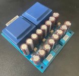
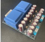
Assembled 😎Sent to production. Grounds of the two sections are not connected on the PCB.
Attachments
Were they supposed to? 🙂And a carbon film resistor in feedback doesn't help either
Alex.
Too sexy....
Sure.in that position is better
As for e, I can't understand why carbon resistors and Y5/Z5 ceramic capacitors (especially smd) are still being produced (except for a few specific items). I don't remember any company I've worked for in the last 20 years using them anywhere.
Alex.
Last edited:
@Tommar, Dale RND55D 3.01kohms gave me the best result for RIV. Much better than Yageo metal film and many others. Kiwame carbon film was tested too, with bad result (too soft). Some say the Dale RND60D is even better, but I haven't tried it.
For tantalum electrolytic capacitors, I would not know if they have a bad effect on the sound in this position. I don't use them.
Wiring is also very important. It's hard for many to believe that, but I have no doubts about it.
For tantalum electrolytic capacitors, I would not know if they have a bad effect on the sound in this position. I don't use them.
Wiring is also very important. It's hard for many to believe that, but I have no doubts about it.
Last edited:
I made in thus thread a test on a dozen of resistors for the Rfb with the op1655/56 opamp...worth a reading imo.
@eclipsevl , hi. The dgnd and agnd pin must seen them together directly the shortest path as possible and the "cleaner" way you can. My 2 cents.
@eclipsevl , hi. The dgnd and agnd pin must seen them together directly the shortest path as possible and the "cleaner" way you can. My 2 cents.
Sorry, didn't get what you mean. Can you clarify please?@eclipsevl , hi. The dgnd and agnd pin must seen them together directly the shortest path as possible and the "cleaner" way you can. My 2 cents.
I think it's more a legend... I find their sound superior to any electrolytics, and can tell never had a problem of reliability.The moment i see the pictures, my hands itches and i imagine myself heating up my soldering iron and removing the tantalum caps immediately without further consideration 🤣
- Home
- Source & Line
- Digital Line Level
- DAC AD1862: Almost THT, I2S input, NOS, R-2R