Thanks @rehanabid and @Michelag . I will look at those R-core options.

It's not critical for my AD1865 board, that has the shift regisers already built in, but for the AD1862 I was thinking about getting the minimal version with current output and no registers, and saving myself the annoying task of soldering those little things... only if it works, of course.
Can you elaborate? I used the RPI GPIO with a PCM5102 DAC in a previous lo-fi project, using this mapping and a standard driver:a CPLD signal consisting of CLK, Latch, Data Left and Data Right
It's not critical for my AD1865 board, that has the shift regisers already built in, but for the AD1862 I was thinking about getting the minimal version with current output and no registers, and saving myself the annoying task of soldering those little things... only if it works, of course.
@gattu marrudu are you from Sardinia?
However, i2s is not a protocol directly accepted by these DAC ICs. They need a conversion first (done in this particular case by shift registers).
I don't know what pcm5102 is using, if it coincides with the ad186x you could try to connect them to the PCM pins, but looks improbable to me.
However, i2s is not a protocol directly accepted by these DAC ICs. They need a conversion first (done in this particular case by shift registers).
I don't know what pcm5102 is using, if it coincides with the ad186x you could try to connect them to the PCM pins, but looks improbable to me.
Sissignore.@gattu marrudu are you from Sardinia?
Thanks for the tips. I'll stick to the script re. shift registers. In the tube world they make a big deal about quality transformers, so I'm always looking for something from reputable vendors, but I guess experimenting with the no-name Chinese R-core will be fine for now.
So I listened the AD811in my new 4 layers itteration pcb N° 5, like the perfum without the smell. Ad1862, so.
To make it short before more description, I find it a strange beast in my setup, there are poors and cons. It makes not better I have found than my main dac opa861 based but dacs are totally different.
It is confortable to listen to with very natural high mids and trebles, colored low midrange with a veil there, false thickness, tamed dynamic or sligthy recess of level in that lower mid/mid-bass. More remarks to come about the voicing and parts later. It makes in my setup a non fatiguing sound with very broad soundstage latterally. Good heigth too. Not ultimatly clear cause the sirup thick low mid. Bass are articulated and good dynamic but lack edge attacks, i.e. too much rounded, like bass made by a bass reflex two ways to illustrate, so not natural.
It has more poors than cons, but too much colored tonal for my setup or taste. It is the champion op for relaxed sound and if you do something else at the same time. Excellent for background or dinner, zero fatigue and headaches. Natural in that context, not for a focused audiophil listening. So sorta of tube sound in the bad side of its description... which a good tube amp is not.
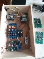
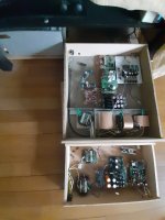
Photograph : new pcb in the little proto box, aside are two V4 4layers pcb on the table. The little proto box aside my main ref Dac with its more complex power supply and digital front end with better clock.
I think thete is room to optimisation with caps and perhaps output resistor. My pre load is 220 pF so I let the 10R PNM serie output resistor. Seems not to oscillate. But the datasheet shows a 22R will be more flat so dynamic for 200 to 250 pF. I am not sure of the datasheet which seems to have a typo. Text says load with 10R output and 100pF shunt and 47kR shunt is flat, but the abak says it should be >=1nF. Grunf member followed the text. with an output impedance certainly equal to the next stage. I prefer a classic voltage impedance adaptation with an impedance lower than 10 times for the source dac by not using the shunt combo.
A good opamp, which high slew rate is not a problem on my pcb. Though I think the 2k impedance of the ad1862 plus the next resistor for compensation is too much for the AD811. Grunf has a very low output impedance as he parrallels several pcm1702 iirc. Btw I used 750R in spite of 1k as he said it was okay too.
So now I would like to feed it with more clear Panasonic FC caps on the AD811 side. And I am populating another board to test op861, ADA4899, OPA828 again with a different external compensation my pcb alllows; and finally the most hard to rule faster op amp op891 !
Edit : AD811 and Analog side of AD1862 have 0.1 uF 0805 Acrylic cap (main are FC on the analog side of the DAC and UKZ 100/25 for the AD811. digital side have 0.01 TDK soft terminal C0G for the digital HF decoupling and very low ESR caps (I play here with BG NX, Pan FR, or polymer APSA caps most of the time)
To make it short before more description, I find it a strange beast in my setup, there are poors and cons. It makes not better I have found than my main dac opa861 based but dacs are totally different.
It is confortable to listen to with very natural high mids and trebles, colored low midrange with a veil there, false thickness, tamed dynamic or sligthy recess of level in that lower mid/mid-bass. More remarks to come about the voicing and parts later. It makes in my setup a non fatiguing sound with very broad soundstage latterally. Good heigth too. Not ultimatly clear cause the sirup thick low mid. Bass are articulated and good dynamic but lack edge attacks, i.e. too much rounded, like bass made by a bass reflex two ways to illustrate, so not natural.
It has more poors than cons, but too much colored tonal for my setup or taste. It is the champion op for relaxed sound and if you do something else at the same time. Excellent for background or dinner, zero fatigue and headaches. Natural in that context, not for a focused audiophil listening. So sorta of tube sound in the bad side of its description... which a good tube amp is not.
Photograph : new pcb in the little proto box, aside are two V4 4layers pcb on the table. The little proto box aside my main ref Dac with its more complex power supply and digital front end with better clock.
I think thete is room to optimisation with caps and perhaps output resistor. My pre load is 220 pF so I let the 10R PNM serie output resistor. Seems not to oscillate. But the datasheet shows a 22R will be more flat so dynamic for 200 to 250 pF. I am not sure of the datasheet which seems to have a typo. Text says load with 10R output and 100pF shunt and 47kR shunt is flat, but the abak says it should be >=1nF. Grunf member followed the text. with an output impedance certainly equal to the next stage. I prefer a classic voltage impedance adaptation with an impedance lower than 10 times for the source dac by not using the shunt combo.
A good opamp, which high slew rate is not a problem on my pcb. Though I think the 2k impedance of the ad1862 plus the next resistor for compensation is too much for the AD811. Grunf has a very low output impedance as he parrallels several pcm1702 iirc. Btw I used 750R in spite of 1k as he said it was okay too.
So now I would like to feed it with more clear Panasonic FC caps on the AD811 side. And I am populating another board to test op861, ADA4899, OPA828 again with a different external compensation my pcb alllows; and finally the most hard to rule faster op amp op891 !
Edit : AD811 and Analog side of AD1862 have 0.1 uF 0805 Acrylic cap (main are FC on the analog side of the DAC and UKZ 100/25 for the AD811. digital side have 0.01 TDK soft terminal C0G for the digital HF decoupling and very low ESR caps (I play here with BG NX, Pan FR, or polymer APSA caps most of the time)
Attachments
Last edited:

I will try later to change my loudspeaker mid serie resistors that are 2 ohms Mundirf Mox with a Supreme which is more on the neutral vs soft the mox gives here.
An important precision is the AD811 was feed with 5.66 V only, the max I could with my previous Miro's board (the 12V side is for the analog of the dac chip).,I plan first to populate a miro's pcb left with 12 V + 10V for the AD811 as THD is sligth reducing going towards 15V (Grünnf iss using 10V to reduce the heat which is a good idea with BJT and thermal noise; I have two smd heatsink I don't use with 5.66V above.
An important precision is the AD811 was feed with 5.66 V only, the max I could with my previous Miro's board (the 12V side is for the analog of the dac chip).,I plan first to populate a miro's pcb left with 12 V + 10V for the AD811 as THD is sligth reducing going towards 15V (Grünnf iss using 10V to reduce the heat which is a good idea with BJT and thermal noise; I have two smd heatsink I don't use with 5.66V above.
Attachments
Last edited:
go with 12/15V. I perceive a difference from 12 to 15 V....So I listened the AD811in my new 4 layers itteration pcb N° 5, like the perfum without the smell. Ad1862, so.
To make it short before more description, I find it a strange beast in my setup, there are poors and cons. It makes not better I have found than my main dac opa861 based but dacs are totally different.
It is confortable to listen to with very natural high mids and trebles, colored low midrange with a veil there, false thickness, tamed dynamic or sligthy recess of level in that lower mid/mid-bass. More remarks to come about the voicing and parts later. It makes in my setup a non fatiguing sound with very broad soundstage latterally. Good heigth too. Not ultimatly clear cause the sirup thick low mid. Bass are articulated and good dynamic but lack edge attacks, i.e. too much rounded, like bass made by a bass reflex two ways to illustrate, so not natural.
It has more poors than cons, but too much colored tonal for my setup or taste. It is the champion op for relaxed sound and if you do something else at the same time. Excellent for background or dinner, zero fatigue and headaches. Natural in that context, not for a focused audiophil listening. So sorta of tube sound in the bad side of its description... which a good tube amp is not.
Photograph : new pcb in the little proto box, aside are two V4 4layers pcb on the table. The little proto box aside my main ref Dac with its more complex power supply and digital front end with better clock.
I think thete is room to optimisation with caps and perhaps output resistor. My pre load is 220 pF so I let the 10R PNM serie output resistor. Seems not to oscillate. But the datasheet shows a 22R will be more flat so dynamic for 200 to 250 pF. I am not sure of the datasheet which seems to have a typo. Text says load with 10R output and 100pF shunt and 47kR shunt is flat, but the abak says it should be >=1nF. Grunf member followed the text. with an output impedance certainly equal to the next stage. I prefer a classic voltage impedance adaptation with an impedance lower than 10 times for the source dac by not using the shunt combo.
A good opamp, which high slew rate is not a problem on my pcb. Though I think the 2k impedance of the ad1862 plus the next resistor for compensation is too much for the AD811. Grunf has a very low output impedance as he parrallels several pcm1702 iirc. Btw I used 750R in spite of 1k as he said it was okay too.
So now I would like to feed it with more clear Panasonic FC caps on the AD811 side. And I am populating another board to test op861, ADA4899, OPA828 again with a different external compensation my pcb alllows; and finally the most hard to rule faster op amp op891 !
Edit : AD811 and Analog side of AD1862 have 0.1 uF 0805 Acrylic cap (main are FC on the analog side of the DAC and UKZ 100/25 for the AD811. digital side have 0.01 TDK soft terminal C0G for the digital HF decoupling and very low ESR caps (I play here with BG NX, Pan FR, or polymer APSA caps most of the time)
I'm collecting parts for the project. I ordered a 2x12v, 2x5v transformer. I already have psu 2. And now I look that I think I need 12v-0-12v and 5v-0-5v outputs. Does it matter what to connect to psu 2?
In my opinion, you ordered a very good transformer. You power PSU2 with voltages from a two-wire system. The voltages you write about (12-0-12 and 5-0-5) you will get at the output of PSU2.
5VAC is too low for 5VDC, even with LDO regulators. Minimum would be 7VAC, I take 8VAC for the LDO. For standard regulators (78XX, 79XX and similar), 9VAC for 5VDC and 14VAC for 12VDC. PSU2 requires separate secondaries for each voltage. So not 12V-0-12V & 5V-0-5V but 12V + 12V & 7V+7V.
Last edited:
Since he's already ordered the transformer, I suggest you try it first and see how the power supply behaves. There's always time for changes 🙂
go with 12/15V. I perceive a difference from 12 to 15 V....
I think I will try first 12V by // another populated miro PS board I have already. It is smd AD811 so thermal dissapation and max level is a bit lower. But the datasheet doesn't forbid the 15V for the smd package. But thermal noise should be avoided in theory.
Pffff, I forgot to purchase the white paste to put the heat-sinks !
Also as the 0.1 uF decoupling on the AD811 are CDE acrylic, it may add another heavy dark layer ! Despite being RF range I am able to hear it in a clock board vs a NP0. So with some op amps that are a little sirup or Elna SII sounding in the low mid high bass, like a op2604 for illustration or an op627, it could be too much, but I have not tested ceramic yet, nore the 0.01 uF advised by Grunf. I have TDK ceramic NP0 in that capacitance to try.
My main loudspeaker is very transparent being aluminium from 100 Hz to 20K hz and a little on the soft side already, but very sligthy. The MKP caps and resistors were voiced on male and female opera singers by a tenor friend of me by ear. The bass is sealed.
Must be noticed I use the Linear Technology PS from Miro and not the WJ Super reg which is sligthy better on the naturalness according @jan.didden benchmark in his publication. But my layout aroubd the AD811 is better. Hard to sort out all of that related to the sound.
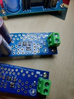
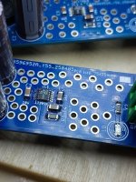
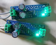
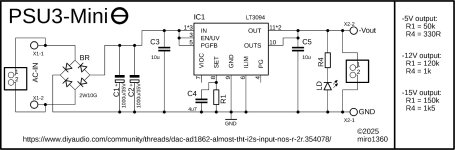
PSU3 Mini (LT3045/LT3094)
Ultralow RMS Noise: 0.8µVRMS (10Hz to 100kHz)
Ultralow Spot Noise: 2nV/√Hz at 10kHz
Ultrahigh PSRR: 76dB at 1MHz
+5V example:
https://eu.mouser.com/Tools/Project/Share?AccessId=5ebc7ee4a8
-5V example:
https://eu.mouser.com/Tools/Project/Share?AccessId=fdc404ea45
For 12V only the R1 and R4 is changed in value.
According to datasheet, be sure to use the exact capacitor parts for C3 and C5.
Very good regulators, but can be difficult to solder due to the small package
It is tested by:
@Sorenm and @zoom777
Attachments
-
 17446790347892017872363629125708.jpg453.1 KB · Views: 133
 -
 17446790116836188816937130525612.jpg552.2 KB · Views: 127
 -
 20250415_085956.jpg521 KB · Views: 135
 -
 diyAudio_PSU3-Mini-Plus_Schematic.jpg133.2 KB · Views: 147
 -
diyAudio_PSU3-Mini-Plus_2025-04-04.zip111.6 KB · Views: 42
-
 diyAudio_PSU3-Mini-Minus_Schematic.jpg148.5 KB · Views: 139
 -
diyAudio_PSU3-Mini-Minus_2025-03-18.zip106.3 KB · Views: 52
5VAC is too low for 5VDC, even with LDO regulators. Minimum would be 7VA
I use 6VAC 3W transformers for the DAC's 5VDC line because transformer is not 100% loaded and its output voltage is not 6VAC but higher.
Also the center-tapped secondary winding with 2 Schottky diode rectifier (instead of diode bridge) reduces the voltage drop, making it sufficient for 5V LDO even with negative line voltage tolerance.
Alex.
6VAC may be enough, but 5VAC is on the edge with diode bridge. The difference with one Shottky diode less is about 0.3V, but depending on the current it can be more. I always calculate that there may be a voltage drop in the network, there is also a ripple on the raw DC, so I secure myself with slightly higher voltages. Besides, I don't buy ready-made transformers, I mostly order good quality custom transformers here ( with static shield+magnetic shield), there is no reason to go to the lower limit. I can order any secondary voltage. I usually check everything with the PSUD2 simulator before ordering.
I also think that the static shield between primary and secondary windings is very important for audio devices. It does not affect the sound like some RF interference filters can, and it performs the same function. The magnetic shield allows me to place the transformer close to the PCBs without a trace of 50Hz hum.
I also think that the static shield between primary and secondary windings is very important for audio devices. It does not affect the sound like some RF interference filters can, and it performs the same function. The magnetic shield allows me to place the transformer close to the PCBs without a trace of 50Hz hum.
Last edited:
but 5VAC is on the edge with diode bridge.
Depends of a transformer. If it provide 6-6.5Vac with real load, all will be OK.
Low-power transformers have a fairly soft load characteristic.
BTW, my 3W (3.2W, to be accurate, this is ~0.5A) trafo have 7.9Vac @ no load, real load is ~0.25A.
With this current trafo's voltage is ~6.5Vac or ~7-8Vdc before LDO. I think if thes trafo will be 5Vac instead of 6Vac, also will be OK.
Alex.
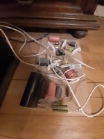
And another little PSU 🙂 I found local source of 35x40 transformers with double 5 or 10v secondary windings. They are rated for 220V so the output is a bit higher that the spec. Voltage regulators are tps7a4701/tps7a3301. The board is 100x86mm

PSU 2 values correction
Hi guys, Vunce informed me about a mistake in the values for +5V in PSU 2.
R15=2k5 and TR1=5k are correct values.
... sorry for any inconvenience
Option 2: Fixed output voltages without trimming:
Trimming part is optional and it may be omitted (R15, TR1, R16, TR2, R17, TR3, R18, TR4). In that case the output voltages are set as fixed and the resistor combinations can be like this example:
R7=1k, R8=320
R9=11k8, R10=36k5
R11=2k94, R12=330
R13=9k, R14=79k6
... attached resistor calculator can be used for those values
... if you find better available values (or with resistors in parallel or series), post it in the forum please (add a note about fixed voltages without trimmers)
Hi miro,
I try to find out from this thread to populate a new PSU2 board for different voltage. Would like to find the values for 10V and 15V.
Question please: how should I choose the trim pot values ? Do you think some values of the pots could allow more than 1.5V trimming ? 2V margin will be better for my application. More trim turns reference needed perhaps ???
AD811 & OPA981 on the bench but I need some Volts.
Thanks,
Edit : how compare the output impedance of your board above VS the PSU2 please ? comon mode rejection ?
Interesting PSU3 Mini!
Just 2 questions:
Many thanks!
Claude (at the beach so perhaps dumber than usual 🙂)
Just 2 questions:
- why not going CRC after the bridge rather than CC? An additional say 5R / 2W resistor could spacialy fit and provide a 31Hz Fc traditional RC filtering
- why is the board so long?
Many thanks!
Claude (at the beach so perhaps dumber than usual 🙂)
- Home
- Source & Line
- Digital Line Level
- DAC AD1862: Almost THT, I2S input, NOS, R-2R