
Great work Iggy! Love to see your passion still burns to get this layout done  .
.
IMO, your choices for I/V section are a win and win!😉
Looking forward to your verification build results.

.IMO, your choices for I/V section are a win and win!😉
Looking forward to your verification build results.
thanks. ADA4899 and opa891 are on the list too. I was curious of the first because of its ultra linear input and it was adviced to me from an italian fellow there.
The second was on my radar, but it will be difficult to make it stable quiet.
But the expensive Vishay smd resitor advised I surmise tp be good or not according the voicing of the rest of the hifi, I also ordered few less expensive tantalum from SEI Stackpole. Smd silver Mica will be tried too. Didn't ordered the very expensive i/v smd cap from G. AD811's bom though.
I planned to design a little pcb to stack in order to try @Bensen discrete I/V he adapted for his ad1862 dac !
Last edited:
Thanks Zoom. Yup, fifth version.
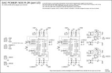
D1/2 😛iggy, pardon...piggy back protection diode that also allows a liitle transcient high frequency garbadge filtering. But its main purpose is to protect the AD1862 output.
Тhe best thing is you can always take them out after an audition 🙂
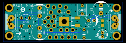
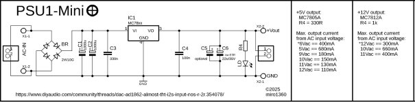
PSU1 Mini (Plus)
PCB size: 75x25mm
Mouser example +5V: https://eu.mouser.com/Tools/Project/Share?AccessId=44b0a47657
Mouser example +12V: https://eu.mouser.com/Tools/Project/Share?AccessId=cbdabd1f70
PCB size: 75x25mm
Mouser example +5V: https://eu.mouser.com/Tools/Project/Share?AccessId=44b0a47657
Mouser example +12V: https://eu.mouser.com/Tools/Project/Share?AccessId=cbdabd1f70
Attachments
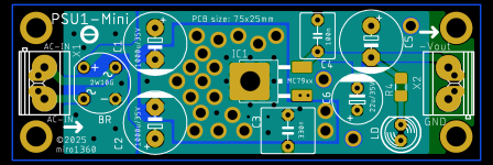
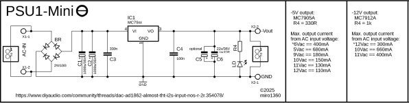
PSU1 Mini (Minus)
PCB size: 75x25mm
Mouser example -5V: https://eu.mouser.com/Tools/Project/Share?AccessId=ad0ec14220
Mouser example -12V: https://eu.mouser.com/Tools/Project/Share?AccessId=63022a8694
PCB size: 75x25mm
Mouser example -5V: https://eu.mouser.com/Tools/Project/Share?AccessId=ad0ec14220
Mouser example -12V: https://eu.mouser.com/Tools/Project/Share?AccessId=63022a8694
Attachments
"Nice mini PSU's @miro1360! I am a big fan of the PSU2 minis"
Me too! They perform very good at a niceee price.

Me too! They perform very good at a niceee price.
I will get my JLCPCb cart ready .. 😀Nice mini PSU's @miro1360....
Any chance of future mini boards for lt3045/lt3094 in the MSE/exposed pin package ... 😊
Тhe best thing is you can always take them out after an audition 🙂
Hi,
It doesn't seem to worry a Thorsten Loesch in his own TDA1541A last shematic, but for sure I will try both w and w/o. I never lost an AD1862 yet... I am not too worry vs a 1 k R in serie before an AD811 inverted input pin for illlustration. And if you ask me I am more worry about tantalum nitride resistor, so which are ceramic body and we know about the ceramic flexing behavior and noise generated with X7R and lower grade (well sometimes more than often some noises or odd harmonics can be nice to ears according the rest of your hifi devices
I don't remember where I read those Shottky diodes can filter peaks current transcient from a current output dac chip that are harmfull for the sound... But it should occur at high frequency current peaks only and where they are the standalone two diodes package is harmless anyway for the stray capacitance countermeasures took on the pcb layout before the first I/V opamp.
As you see, a cap to ground or a cap + resistor to ground can be added as well before the I/V opamp for a passive pre filter too in order to add to the 6dB filtering of the op amp. It is NOS so there is not post Sallen-Key op amp active filtering.
Btw, if I was to add a further filtering stage it would be a passive one VS an op amp one. (I remember an input from you about that, also EUVL...)
Last edited:
Very high chance, almost 100%, it will be ready in a short time 😀Nice mini PSU's @miro1360! I am a big fan of the PSU2 minis.
Any chance of future mini boards for lt3045/lt3094 in the MSE/exposed pin package ... 😊
They look really very good and with AD1862 (and not only) are working great 😉"Nice mini PSU's @miro1360! I am a big fan of the PSU2 minis"
Me too! They perform very good at a niceee price.
Hello everyone!
Guys, does anyone have a gerber file of the EUVL exhaust either on the OU 844 or on the 861?
Please share
Guys, does anyone have a gerber file of the EUVL exhaust either on the OU 844 or on the 861?
Please share
PSU1 Mini (Minus)
PCB size: 75x25mm
Mouser example -5V: https://eu.mouser.com/Tools/Project/Share?AccessId=ad0ec14220
Mouser example -12V: https://eu.mouser.com/Tools/Project/Share?AccessId=63022a8694
Hi,
Is now vias in pad free at JLPCB ?
Have you thougth about ading a serie 10R/1W carbon between the diode bridge and the first smoothing cap ? It work very fine.
I am glad now the with the 78/79xx the last reservoir cap near the load is bigger than the one after the reg output pin ! 🙂
Could anyone help me to find the post number to get this version for pcm63?
Thx
Last edited:
It is buried deep in this thread.
@iitzex , have fun.
@iitzex , have fun.
Attachments
-
diyAudio_PCM63P_DAC_v1.4_uf.l_jlsounds-notFlipped_align_2022-12-22.zip771 KB · Views: 43
-
 diyAudio_PCM63P_DAC_v1.4_uf.l_jlsounds-notFlipped_align_PCB.jpg426.5 KB · Views: 121
 -
 diyAudio_PCM63P_DAC_v1.4_uf.l_jlsounds-notFlipped_align_Schematic1.jpg281.2 KB · Views: 128
 -
 diyAudio_PCM63P_DAC_v1.4_uf.l_jlsounds-notFlipped_align_Schematic2.jpg162.7 KB · Views: 128
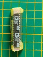
After lurking on this thread for. A while, I decided to build my own MIRO AD1862 dac.
Paddy Garcia helped me to get the AD1862 DAC chips. Many thanks for that. 🙏👍.
For power I have some modified Jung/Didden boards.
Now what I need is the DAC PCB board. Anyone who can help me out with that?
I'm a bit afraid to solder the shift registers.
I don't want to go the route to use the JLSound boards. (Prefer to use some more general like amanero, u30 or ...)
I don't know what options that I have?
Is the CPLD board a valid option?
Attachments
Hi,
AD1862 is no I2S input compatible so you need logic after I2S output boards like Amanero is.
Miro's cpld is an option as the offers here of I2S to AD1862 diy pcb boards already soldered.. But if you're afraid to solder the shift registers, be aware the cpld is way tinnier and harder to soldering. So go for an already soldered board instead a raw board to populate.
There is not particular difficulty with the shift-registers. You just need using flux and magnyfing glass and look at some Youtube soldering HOW TOs.
Be aware too, Amanero's clones are not very good on the clock quality.
This: 🙂I don't know what options that I have?
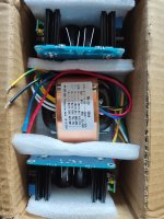
New arrivals, 10x ISO modules with reclock boards in black 😎

- Home
- Source & Line
- Digital Line Level
- DAC AD1862: Almost THT, I2S input, NOS, R-2R