With a proper quality transformer with blind winding between primary amd secondary, and with magnetic shield, it shouldn't be as critical. BUT, properly done toroids are scarce so i'd follow the advice above. We are lucky there are amazing toroids from Trafomatic here in Serbia.

If anyone interested for AD1862 chips i am selling 2 pairs
https://www.diyaudio.com/community/threads/ad1862-2-pairs-new.412359/#post-7675235
https://www.diyaudio.com/community/threads/ad1862-2-pairs-new.412359/#post-7675235
Friends, I'm studying hard the thread.
Naive question: is there a way to make only one build, and make the dac switchable between ad1862 and tda1541 simultaneous mode?
Really my wife is going to kick me out if I build 2 enclosures this time
Naive question: is there a way to make only one build, and make the dac switchable between ad1862 and tda1541 simultaneous mode?
Really my wife is going to kick me out if I build 2 enclosures this time
 .
.with all the various power supplies for each DAC ...... and their transformers.... your single chassis will be as big as two smaller chassis 🤣
Hey colleagues, please show me some lineage!!! Of how your CD players, TVs, raspberries and Nas are plugged to this wonderful dac via USB, spdif, coax!!!
Trying to figure out how to put it ad good use apart from my old CD player!
PS. I've a qobuz sub now, I'd like to use that with this dac!
Trying to figure out how to put it ad good use apart from my old CD player!
PS. I've a qobuz sub now, I'd like to use that with this dac!
Another thing I can't understand is about the CPLD converter... Is it needed with the ad1862? I understand it is needed for the tda1541 in simultaneous mode, yet I can't see the boards in your ad1862 build...
What would be its function with the ad1862?
What would be its function with the ad1862?
You should start at page one of this thread with a notebook and pencil ready for note taking, there are many, many builds and tons of pictures showing how diyers implement the AD1862 chip plus several others. Go to the Electrodac link Miro attached in post#1, all the info you need to start is there. Download and read the AD1862 datasheet. 😉
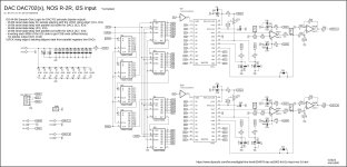
DAC702 prototype schematic 😎
Glue Logic piece ... at least in simulator it works
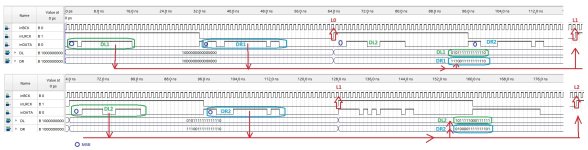
I2S 64-Bit Sample Glue Logic for DAC702 principle (bipolar output) in theory:
Glue Logic piece ... at least in simulator it works
I2S 64-Bit Sample Glue Logic for DAC702 principle (bipolar output) in theory:
- 15-Bit serial data delay for sample aligning with the LRCK rising edge* (IC1, IC2)
- 16-Bit serial data delay with parallel out buffer for DAC1 (IC3, IC4)
- 16-Bit serial data delay (IC5, IC6)
- 16-Bit serial data delay with parallel out buffer for DAC2 (IC7, IC8)
- Inverting each MSB of the I2S code to get COB code (offset binary) for bipolar output (IC9, IC10)
- *LRCK rising edge is latching aligned data from parallel registers into DACs
Attachments
😗 this looks like a nice project coming , very soon I hope....😉
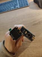
Guys, I buy arduino nano and oled display for her but I don't get it how to connect arduino and ours Dac? - There is a mention about LRCK pin on Dac but it needs to be more pins from arduino. Who can help with connection? The code is he:
DAC AD1862: Almost THT, I2S input, NOS, R-2R | Page 370 | diyAudio
I want to see the info about sample rate on display. I need for the Jlsound and Amanero transports.
Thanks!
DAC AD1862: Almost THT, I2S input, NOS, R-2R | Page 370 | diyAudio
I want to see the info about sample rate on display. I need for the Jlsound and Amanero transports.
Thanks!
Attachments
Last edited:
@sworder84
Display is connected on fast I2C output from arduino nano (pins SDA (A4) and SCL (A5) ... plus voltage and gnd pins) ... check if your display is for 3.3V or 5V power supply.
LRCK is connected on pin D2. GND from DAC must be also connected with arduino GND.
Display is connected on fast I2C output from arduino nano (pins SDA (A4) and SCL (A5) ... plus voltage and gnd pins) ... check if your display is for 3.3V or 5V power supply.
LRCK is connected on pin D2. GND from DAC must be also connected with arduino GND.
Attachments
I was started arduino and oled yesterday (different samples).
@miro1360 thanks for answer, I will try to connect with AD1865.
@miro1360 thanks for answer, I will try to connect with AD1865.
Hoping to try building a TDA1540 and TDA1541A dac. If using the CPDL convertor I can bypass the glue logic section for the TDA1541A correct?
@gsrchrisu, if you are referring to using programmed CPLD converter as created by Miro for TDA1540 and TDA1541, yes it is meant to replace the glue logic section for simultaneous operation.
Anyone tried AD1862 in multichannel configuration. As I know there is only a few USB-I2s multichannel boards
1.https://www.minidsp.com/products/usb-audio-interface/mchstreamer
2.https://www.diyinhk.com/shop/audio-kits/142-2302-xmos-multichannel-high-quality-usb-tofrom-i2sdsd-spdif-pcb.html#/67-xmos_firmware-192k_8ch_out_8ch_in_spdif_out/111-usb_cable-null/141-fifo_option-null
1.https://www.minidsp.com/products/usb-audio-interface/mchstreamer
2.https://www.diyinhk.com/shop/audio-kits/142-2302-xmos-multichannel-high-quality-usb-tofrom-i2sdsd-spdif-pcb.html#/67-xmos_firmware-192k_8ch_out_8ch_in_spdif_out/111-usb_cable-null/141-fifo_option-null
- Home
- Source & Line
- Digital Line Level
- DAC AD1862: Almost THT, I2S input, NOS, R-2R