Well, I have just put in the LM6171 after Miro's proposal and i didn't swap it ever again. Maybe I'll try 1611 or 1656 in the near future, as I plan to send out a Mouser order.
Ernst
I have tried opa1611, opa1656, opa1612, lm6172, lme49990, lme49720, muses8920 and ad797, among some others.
So far, my favorite op amps have been muse01, sparkoslab ss3602 and lm6171. These are in the same league, far more open, natural and musical than any others. A close second is NE5532. Everything else that I have tried fall into the third tier, which is far behind tiers 1 and 2.
Cheers!
Last edited:
Hi miro, what are the board dimensions JLCPCB didn't find them...I2SoverUSB not flipped (pin-headers installed on the bottom side on I2SoverUSB) ... the heatsink and USB connector are on the TOP 🙂
Attachments
If you are ordering PCBs with integrated i2soverusb
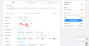
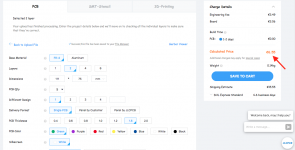
"There can be problem with jlcpcb viewer after gerbers uploading. IDK why jlcpcb has problem to show the preview for these files, because pcbway is working fine. But the file is uploaded successfuly, so enter dimensions manually: 111x75 and it should work 😀"
"There can be problem with jlcpcb viewer after gerbers uploading. IDK why jlcpcb has problem to show the preview for these files, because pcbway is working fine. But the file is uploaded successfuly, so enter dimensions manually: 111x75 and it should work 😀"
Questions about power:
If I understand correctly, the I2S vIII board can take a 5v power supply from the AD1862 DAC board. Am I able to run all of the 5v supplies from one bipolar PSU, or does the USB need to be kept independent from the crystal + DAC?
Hi asilker.
I asked similar questions before.
I hope #2592-#2600 helps.
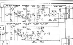
You can try add 2R2 resistors on power railsIt is very good prevention against PSU oscillation for these regulators. (The picture shows only +-5V, but do it also for +-12V PSU).
But first try the LM6171 in I/V 😉
Hi miro, thank you for suggesting checking power supply oscillation.
I checked all of my boards, and was surprised to see the +/-5 board oscillating with a peek to peek voltage difference of 160mv! After further investigation, it turned out to be exactly like what you said: too high capacitance at output puts the power supply into oscillation. I removed 8200uf and the big oscillation was gone. But there was still too much voltage fluctuation to my liking. So I removed all output capacitors except one 4.7uf film. This has brought the voltage differences down to 20 mv. This is as far as I can go right now.
The LT3045s are supposed to be able to do better than 1 mv. I wonder if putting in 2r2 resistors can further reduce the voltage fluctuation? Or perhaps the boards are already functioning according to specs. The 20 mv Vpp I see could just be measurement errors?
What are the measured voltage fluctuations of PSU1 and PSU2?
The LT3045 data sheet is worth a peek and may be helpful when it comes to load capacitance. Check out page 15 for the minimum of a low ESR ceramic of at least 10uF hard up to the output pin of the reg. Bear in mind if appropriate that a series resistance after that of 2R2 will make the load regulation poor particularly at low frequencies and everything will depend on the quality of the subsequent capacitor. It will destroy many of the benefits of using the LT3045 in the first place.
John
Thank you John. I used to have a 22uf ceramic capacitor at the output, in addition to a 1000uf and a 8200uf aluminum cap. After removing both the 1000uf and 8200uf, I still wasn't happy with the measurement results. So I removed the 22uf ceramic as well and put in a 4.7 film in its place. This has given me better results. I will order some 10uf ceramic to try next time
Sorry, I was wrong when saying LT3045. The board in question actually has LT3042s on it. The LT3045s are on my other power boards that also have 20 mv Vpp. The LT3042 data sheet suggests using a minimum of 4.7uf ceramic at output. That's why I thought the 4.7uf film might work since I don't have a 4.7uf ceramic on hand.
@diyiggy Should I link easyDAC on the main page? It has many SMD components 😀
@Hidy Nice jab for these LDO regulators 😉 Many people buy these ready-made LDO super regulators and will connect it as super oscillators (including LM317/337) 😀 All the benefits of using these super regulators are destroyed as soon as they are used far from the device (long wires, connectors resistance). Each device should thus have its own regulator on the PCB as close as possible in order to gain all the benefits 😀 ... The benefit could be increased by using thicker short wires and solder it on both sides of PCBs. Then the values of the filter capacitors must be reduced for each device to a non-oscillating value 🙄
Now you know why I like the stability of 78/79xx regulators. They can have as much output capacitance as you like (it is pretty stable due emitter folower stage with no gain) 🙂
Maybe I could share my super regulator resistant to a high capacity
However, its construction is expensive and therefore it will not gain much interest
miroPSU+
Is anyone busy building Euvl/Ripster discrete IV yet? Just finally got my Susumu smd R and I shall hopefully start them soon.
hummm I missed that... too much things to do, not saying a tube stage to come in the waiting list... But Winter is coming  ....and soon I hope a waited Mouser package on a dragon back 😎 (due to the cop 26 CO2 restrictions)
....and soon I hope a waited Mouser package on a dragon back 😎 (due to the cop 26 CO2 restrictions)
Last edited:
including LM317/337) 😀 All the benefits of using these super regulators are destroyed as soon as they are used far from the device (long wires, connectors resistance).
Miro, please clarify: you said a 2R2 series resistor would help, but now you say even the series resistance of a long connection would harm...?
Also I am interested to learn how to avoid problems with the 317/337s as I use these a lot. Normally I would put a medium ESR 10~47u at the output, or use tants, but not ceramics or films. If I have the load far I put a local 47u at the load, and sometimes between the 2 caps an LC. For example: 10uF->317->10uF->100uH->22uF->wire-connection-and/or-1R->47uF->load. What else can be done?
Last edited:
... as said a serie resistor up to 3R3 even if long pcb trace... but then you have to decouple near the load this time with a low ESR 47 uF//0.1 to 1 uF (not too low to avoid oscillation according the oap you use). Solid tantal could do at the reg output pins but it's so much colored than you don't want !
After such 78/79xx and LM reg, a bad ESR 220 uF cap works fine w/o serie resistor on the output legs (gnd-out), but at the input legs (in-gnd) a good ESR cap (100 uf and more) if the main power supply smoothing cap are a little far like 10 to 15 cm. I don't like too much Silmic Elna caps but here at the input of those old chips the Silmic II in low voltage range (<=16V) is ok.
my two cents and at least what my ears said to me.
Try to look for Nazar LM317 fast reg shematic here on DIYAUDIO
Last edited:
@diyiggy Should I link easyDAC on the main page? It has many SMD components 😀
What's wrong with smd ? 😕 .... till you put big enough trace for smd caps -1205 size and more-

@jpk73 This resistor helps against oscillation. There is nothing worse as oscillated PSU 😀 ... on the other hand the resistance decreases the quality of load regulation.
It is not problem to stabilize the PSU. Problem can happen when it is connected to a device which uses additional low-esr filtration capacitors. Audio devices like low-esr filter capacitors and this can be a problem for the PSU:
It is not problem to stabilize the PSU. Problem can happen when it is connected to a device which uses additional low-esr filtration capacitors. Audio devices like low-esr filter capacitors and this can be a problem for the PSU:
Last edited:
Having long leads to the power supply can result in oscillations generated by the AD844 feeding the output device. This is if a resistor isn't in series with the 470pF cap from pin5. Try taking off this 470pf capacitor. If the oscillation quits then the resistor can be necessary in your configuration.
Miro, I'm trying to figure out the differences between your PSU 1 & 2. I understand that 2 features adjustable voltages with trimmers. Is that flexibility the main difference, or do the regulators in PSU 2 somehow do a better job?
Thanks for all the help. This build will feature a few "firsts" for me and I'm excited to get started.
Thanks for all the help. This build will feature a few "firsts" for me and I'm excited to get started.
@asilker IDK if the sound is better with PSU 2. I created it for DIY community, because someone can decide to test which one "sounds" better 🙂
Both can be configured with different regulators. See this mod from @jimk04 for PSU 1 #2073 😉 There are many options.
What sounds better is hard to answer. I only know, that 78/79xx regulators were used in many premium R-2R DACs in times, when the sound fidelity was the highest priority for premium players (Teac, Yamaha, ...), Sony sometimes used a discrete PSU, but again with emitter folower stage + solid capacitor filtration, why? Because audio like big capacitors
What about cloning some discrete PSU from Sony?
Attachments
Last edited:
- Home
- Source & Line
- Digital Line Level
- DAC AD1862: Almost THT, I2S input, NOS, R-2R